MotionView User's Guide

Deformable Strut

Deformable Strut

Previous topic Next topic Expand/collapse all hidden text  

Deformable Strut

Previous topic Next topic JavaScript is required for expanding text JavaScript is required for the print function  

Introduction

In the Deformable Strut system, the strut rod is modeled by beams and the strut tube to strut rod joint is modeled by a point to deformable curve constraint.  This allows the strut to bend under load and captures the camber change due to lateral force common to strut suspensions.
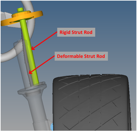
deformable_strut_system_example_mv

Deformable Strut System

The deformable strut system is available in the MDLLIB’s MacPherson Strut front and rear suspensions and the Quadlink rear suspension.  To use deformable struts in a model, simply select Deformable strut from the Front-struts or Rear-struts option menus in the Assembly Wizard as shown below:
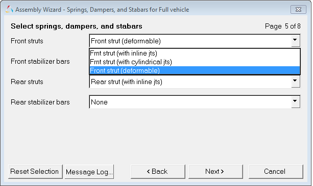
assembly_wizard_deformable_strut_mv

Wizard Selection – Deformable Strut

Users with existing suspension or full vehicle models that wish to use the deformable strut can import the system definition sysdef_deformable_strut from:

$ALTAIR_HOME/hw/mdl/mdllib/Libs/Models/Frnt_strut/deformable_strut.mdl

You can use MotionView’s system Import feature by following the steps below:

1.Select the model, or system within your model, to which you want to add the deformable strut.
2.Select the Import/Export tab in the panel area of MotionView.
3.Pick the Import radio button.
4.Select the file:
$ALTAIR_HOME/hw/mdl/mdllib/Libs/Models/Frnt_strut/deformable_strut.mdl.
5.Press the Import button.

System Options

The deformable strut includes options for attaching to other systems and an option to set the system compliance.

hmtoggle_plus1Attachments

The Deformable Strut system takes as input bodies and points to which the upper and lower ends of the strut attach to, and points defining the upper and lower strut and spring locations.

Attachment Varname

Label

Entity Type

Description

b_upper_att

"Strut upr att body"

Body or BodyPair

Body to which the upper part of the strut attaches.

b_lower_att

"Strut lwr att body"

Body or BodyPair

Body to which the lower part of the strut attaches.

p_strut_rod_upr

“Top of strut rod”

Point or PointPair

Point location where the upper strut rod attaches.

p_strut_tube_lwr

“Bottom of strut tube”

Point or PointPair

Point location where the bottom of the strut tube attaches.

p_spr_upr

"Top of spring"

Point or PointPair

Point giving the location of the upper spring.

p_spr_lwr

"Bottom of spring”

Point or PointPair

Point giving the location of the lower spring.

hmtoggle_plus1Compliant Option

The Deformable Strut system provides an option called Compliant.  Setting this option to No switches the upper strut joints to non-compliant universal joints.  The default state is Yes (On).

deformable_strut_compliant_option_mv

Deformable Strut System - Options

hmtoggle_plus1Strut Rod and Tube Dimensions

The Deformable Strut system includes parameters for setting the strut rod and strut tube lengths.  All of the point locations are parametric to these parameters.  The length values are set using the Strut rod length and Strut tube length fields found in the dataset within in the deformable strut system.  Additionally, the diameter of the strut rod can be set using the field labeled Strut Rod Diameter.  The Strut length field is calculated automatically through an expression which uses the strut end points.

deformable_strut_rod_tube_dimensions_mv

hmtoggle_plus1Points

The points defined in the deformable strut exist primarily to:

Connect the strut rod to the strut tube through a joint
Form a polybeam

All of the points are parametric to the upper and lower strut attachment points, the strut total length, the strut rod length, and the strut tube length.  Each of these points are described in detail below.

deformable_strut_principal_points_example_mv

Principal Points - Deformable Strut

Strut Rod Lower

The Strut Rod Lower is a PointPair with the left side being the symmetric side.  It is the lowest end of a strut rod in a deformable strut and is located within the strut tube.  The expression for calculating the coordinates for this point are shown in the table below:

Coordinate

Expression

X

p_strut_rod_upr.l.x + (p_strut_tube_lwr.l.x-p_strut_rod_upr.l.x)/ds_strut.strut_len.value*ds_strut.strut_rod_len.value

Y

p_strut_rod_upr.l.y + (p_strut_tube_lwr.l.y-p_strut_rod_upr.l.y)/ds_strut.strut_len.value*ds_strut.strut_rod_len.value

Z

p_strut_rod_upr.l.z + (p_strut_tube_lwr.l.z-p_strut_rod_upr.l.z)/ds_strut.strut_len.value*ds_strut.strut_rod_len.value

The variables used in the expression above are described below:

Expression

Model Equivalent

p_strut_rod_upr.l.x

X coordinate of the Upper Strut Attachment Point – Left

p_strut_tube_lwr.l.x

X coordinate of the Lower Strut Attachment Point – Left

p_strut_rod_upr.l.y

Y coordinate of the Upper Strut Attachment Point – Left

p_strut_tube_lwr.l.y

Y coordinate of the Lower Strut Attachment Point – Left

p_strut_rod_upr.l.z

Z coordinate of the Upper Strut Attachment Point – Left

p_strut_tube_lwr.l.z

Z coordinate of the Lower Strut Attachment Point – Left

ds_strut.strut_len.value

Total strut length value defined in the dataset

ds_strut.strut_rod_len.value

Strut rod length value defined in the dataset

As seen from the above table, the coordinates are determined by the upper and lower strut locations, the total strut length, and the strut rod length.

Strut Tube Upper

The Strut Tube Upper is a PointPair with the left side being the symmetric side.  It is the top end of the strut tube in a deformable strut.

The expression for calculating the coordinates for this point are shown in table below:

Coordinate

Expression

X

p_strut_tube_lwr.l.x + (p_strut_rod_upr.l.x-p_strut_tube_lwr.l.x)/ds_strut.strut_len.value*ds_strut.strut_tube_len.value

Y

p_strut_tube_lwr.l.y + (p_strut_rod_upr.l.y-p_strut_tube_lwr.l.y)/ds_strut.strut_len.value*ds_strut.strut_tube_len.value

Z

p_strut_tube_lwr.l.z + (p_strut_rod_upr.l.z-p_strut_tube_lwr.l.z)/ds_strut.strut_len.value*ds_strut.strut_tube_len.value

The variables used in the expression above are described below:

Expression

Model Equivalent

p_strut_rod_upr.l.x

X coordinate of the Upper Strut Attachment Point – Left

p_strut_tube_lwr.l.x

X coordinate of the Lower Strut Attachment Point – Left

p_strut_rod_upr.l.y

Y coordinate of the Upper Strut Attachment Point – Left

p_strut_tube_lwr.l.y

Y coordinate of the Lower Strut Attachment Point – Left

p_strut_rod_upr.l.z

Z coordinate of the Upper Strut Attachment Point – Left

p_strut_tube_lwr.l.z

Z coordinate of the Lower Strut Attachment Point – Left

ds_strut.strut_len.value

Total strut length value defined in the dataset

ds_strut.strut_tube_len.value

Strut tube length value defined in the dataset

Flexible Rod - Left

The Flexible Rod points are a set of five points located equidistant from each other between the strut rod upper and strut rod lower points.  The points are used to connect the individual beams in the polybeam –left and also define the control points for the deformable curve - left.  Their label is suffixed with a number ranging from 0 to 4.  For example, the point “Left Flexible Rod0” is the first point, “Left Flexible Rod1” the second point, and so on with the “Left Flexible Rod4” being the last.

Since the polybeam cannot be modeled as a pair, the points are defined individually for each side (instead of being pairs).

The expressions used to calculate the coordinate values for the left side are shown below:

Coordinate

Expression

X

p_strut_rod_upr.l.x + (p_strut_rod_lwr.l.x-p_strut_rod_upr.l.x) * n

Y

p_strut_rod_upr.l.y + (p_strut_rod_lwr.l.y-p_strut_rod_upr.l.y) * n

Z

p_strut_rod_upr.l.z + (p_strut_rod_lwr.l.z-p_strut_rod_upr.l.z) * n

The variables used in the expression above are described below:

Expression

Model Equivalent

p_strut_rod_upr.l.x

X coordinate of the Upper Strut Attachment Point – Left

p_strut_rod_lwr..l.x

X coordinate of the Lower Strut Rod – Left

p_strut_rod_upr.l.y

Y coordinate of the Upper Strut Attachment Point – Left

p_strut_rod_lwr.l.y

Y coordinate of the Lower Strut Rod – Left

p_strut_rod_upr.l.z

Z coordinate of the Upper Strut Attachment Point – Left

p_strut_rod_lwr.l.z

Z coordinate of the Lower Strut Rod – Left

n

The multiplication ratio.  This is calculated as the nth point divided by the number of points including the strut rod upper.  For the first point it is 1/6, second point 2/6 etc.

Flexible Rod - Right

The flexible rod points on the right are defined similar to the flexible rod points on the left.  They use the points on the right side to calculate their locations.

The expressions used to calculate the coordinate values for the right side are shown below:

Coordinate

Expression

X

p_strut_rod_upr.r.x + (p_strut_rod_lwr.r.x-p_strut_rod_upr.r.x) * n

Y

p_strut_rod_upr.r.y + (p_strut_rod_lwr.r.y-p_strut_rod_upr.r.y) * n

Z

p_strut_rod_upr.r.z + (p_strut_rod_lwr.r.z-p_strut_rod_upr.r.z) * n

The variables used in the expression above are described below:

Expression

Model Equivalent

p_strut_rod_upr.r.x

X coordinate of the Upper Strut Attachment Point – Right

p_strut_rod_lwr.r.x

X coordinate of the Lower Strut Rod – Right

p_strut_rod_upr.r.y

Y coordinate of the Upper Strut Attachment Point – Right

p_strut_rod_lwr.r.y

Y coordinate of the Lower Strut Rod – Right

p_strut_rod_upr.r.z

Z coordinate of the Upper Strut Attachment Point – Right

p_strut_rod_lwr.r.z

Z coordinate of the Lower Strut Rod – Right

n

The multiplication ratio.  This is calculated as the nth point divided by the number of points including the strut rod upper.  For the first point it is 1/6, second point 2/6 etc.

Strut Tube CG

The Strut Tube CG point is a PointPair used to locate the CG location for the Strut tube body and is a parametric value. The values are symmetric with the values on the LEFT being used on both sides.

The coordinates use the following expressions:

Coordinate

Expression

X

p_strut_tube_lwr.l.x / 2 + p_strut_tube_upr.l.x / 2

Y

p_strut_tube_lwr.l.y / 2 + p_strut_tube_upr.l.y / 2

Z

p_strut_tube_lwr.l.z / 2 + p_strut_tube_upr.l.z / 2

The variables used in the expression above are described below:

Expression

Model Equivalent

p_strut_tube_upr.l.x

X coordinate of the Upper Strut Tube Point – Left

p_strut_tube_lwr.l.x

X coordinate of the Lower Strut Attachment Point – Left

p_strut_tube_upr.l.y

Y coordinate of the Upper Strut Tube Point – Left

p_strut_tube_lwr.l.y

Y coordinate of the Lower Strut Attachment Point – Left

p_strut_tube_upr.l.z

Z coordinate of the Upper Strut Tube Point – Left

p_strut_tube_lwr.l.z

Z coordinate of the Lower Strut Attachment Point – Left

hmtoggle_plus1PolyBeams

The Deformable Strut system consists of two polybeams, one for each side, that simulate the behavior of the strut rod.  The polybeam is defined with a circular section whose diameter is parametric and is set through the dataset option labeled “Strut rod diameter”.

deformable_strut_polybeam_example_mv

PolyBeam - Deformable Strut

The table below describes the connections for both polybeams:

Label

Type

Point Connectivity

Notes

Strut Rod - Left

Circular

Point 1

Strut rod upper left


Point 2

Flexible Rod Left - 0


Point 3

Flexible Rod Left - 1


Point 4

Flexible Rod Left - 2


Point 5

Flexible Rod Left - 3


Point 6

Flexible Rod Left - 4


Point 7

Strut rod lower left


Strut Rod - Right

Circular

Point 1

Strut rod upper right


Point 2

Flexible Rod Right - 0


Point 3

Flexible Rod Right - 1


Point 4

Flexible Rod Right - 2


Point 5

Flexible Rod Right - 3


Point 6

Flexible Rod Right - 4


Point 7

Strut rod lower right


The table below describes the properties for the polybeams:

Polybeam

Rho

E (Young’s modulus - N/mm2)

G
(Shear modulus - N/mm2)

OD (mm)

ID (mm)

AS (mm)

CRatio

Notes

Strut Rod - Left

1e-6

207000

80000

18

0

1

0.01


Strut Rod - Right

1e-6

207000

80000

18

0

1

0.01


hmtoggle_plus1Deformable Curve

The Deformable Strut system consists of two deformable curves – one for each side. The curve determines the path followed by the strut tube upper point when connected through an advanced joint. The control points for the curve are determined by markers.

deformable_strut_deformable_curve_example_mv

Deformable Curve - Deformable Strut

The table below describes the deformable curves:

Label

Data Type

Left end type

Right end type

Connectivity

Notes

Deformable Curve - Left

Marker

Natural

Natural

Marker 1

Left strut 1


Marker 2

Left strut 2


Marker 3

Left strut 3


Marker 4

Left strut 4


Marker 5

Left strut 5


Marker 6

Left strut 6


Marker 7

Left strut 7


Deformable Curve - Right

Marker

Natural

Natural

Marker 1

Right strut 1


Marker 2

Right strut 2


Marker 3

Right strut 3


Marker 4

Right strut 4


Marker 5

Right strut 5


Marker 6

Right strut 6


Marker 7

Right strut 7


hmtoggle_plus1Markers

The Deformable Strut system consists of fifteen markers.  Fourteen of these are split equally on each side and are used to define the deformable curve.  The remaining marker is a pair and is used to orient the coil spring.

The table below describes the connections for markers:

Label

Type

Body 1

Origin

Notes

Strut Left - 1

Single

Strut Rod - Left-Body 0

Flexible Rod Left - 0


Strut Left - 2

Single

Strut Rod - Left-Body 1

Flexible Rod Left - 1


Strut Left - 3

Single

Strut Rod - Left-Body 2

Flexible Rod Left - 2


Strut Left - 4

Single

Strut Rod - Left-Body 3

Flexible Rod Left - 3


Strut Left - 5

Single

Strut Rod - Left-Body 4

Flexible Rod Left - 4


Strut Left - 6

Single

Strut Rod - Left-Body 5

Strut rod lower - left


Strut Left - 7

Single

Strut Rod - Left-Body 6

Strut tube CG - left


Strut Right - 1

Single

Strut Rod - Right-Body 0

Flexible Rod Right - 0


Strut Right - 2

Single

Strut Rod - Right-Body 1

Flexible Rod Right - 1


Strut Right - 3

Single

Strut Rod - Right-Body 2

Flexible Rod Right - 2


Strut Right - 4

Single

Strut Rod - Right-Body 3

Flexible Rod Right - 3


Strut Right - 5

Single

Strut Rod - Right-Body 4

Flexible Rod Right - 4


Strut Right - 6

Single

Strut Rod - Right-Body 5

Strut rod lower - right


Strut Right - 7

Single

Strut Rod - Right-Body 6

Strut tube CG - right


Coil Spring Orientation

Pair

Strut tube (lwr strut)

Spring lower point


hmtoggle_plus1Advanced Joints

The Deformable Strut system consists of two advanced joints to connect each side of the strut tube to the deformable curve.

The table below describes the advanced joint connections:

Label

Type

Body 1

Point

Deformable Curve

Notes

Strut Tube to Deformable Curve - Left

PointToDeformableCurveJoint

Strut Tube Lower Left

Strut Tube Upper Left

Left Deformable Curve


Strut Tube to Deformable Curve - Right

PointToDeformableCurveJoint

Strut Tube Lower Right

Strut Tube Upper Right

Right Deformable Curve


hmtoggle_plus1Bodies

The Deformable Strut system consists of a two bodies as shown in the figure below:

deformable_strut_bodies_example_mv

Bodies - Deformable Strut

The Strut Tube (Lower Strut) simulates the tube in a deformable strut that generally stores fluid.

When internal bumpstops are included in the suspension, they are attached with the help of the BodyPair - Attachment for internal bumpstops.

The default mass and inertia properties for the bodies are shown below:

Body

Mass (Kg)

Ixx (Kg/mm2)

Iyy (Kg/mm2)

Izz (Kg/mm2)

Notes

Strut Tube

1

655.3

655.3

655.3


Attachment for internal bumpstops

0

0

0

0


hmtoggle_plus1Joints

The Deformable Strut system primarily consists of joints connecting the strut tube to the strut rod and the strut tube to the knuckle.

deformable_strut_joints_example_mv

Joints - Deformable Strut

The table below describes the joints with the bodies and points they are resolved to:

Label

Type

Body 1

Body 2

Point

Notes

Piston Rod - Left

Cylindrical

Left Strut Rod-Body 6

Strut Tube Lower Left

Strut Rod Lower Left


Piston Rod - Right

Cylindrical

Right Strut Rod-Body 6

Strut Tube Lower Right

Strut Rod Lower Right


Strut Upper - Left

Universal

Vehicle/ Ground

Strut Rod –Left-Body 0

Strut Rod Upper Left


Strut Upper - Right

Universal

Vehicle/ Ground

Strut Rod –Right-Body 0

Strut Rod Upper Right


Bumpstop att to strut rod - Left

Fixed

Strut Rod - Left-Body 0

Attachment for internal bumpstops - Left

Strut Rod Upper Left


Bumpstop att to strut rod - Right

Fixed

Strut Rod - Right-Body 0

Attachment for internal bumpstops - Right

Strut Rod Upper Right


Strut tube bottom

Fixed

Strut Tube Lower

Knuckle

Strut Tube Lower


Note - The cylindrical joints connecting the polybeam strut rod and strut tube, the universal joints connecting the vehicle to the strut rod and the fixed joints connecting the strut rod to the bumpstop attachments are not modeled as pairs.

hmtoggle_plus1Bushings

The bushings are located at the upper ends of the deformable strut.

deformable_strut_bushings_example_mv

Bushings - Deformable Strut

The table below describes them:

Label

Type

Body 1

Body 2

Point

Notes

Strut Upper - Left

Universal

Subframe, Vehicle Body or Ground

Strut rod
Body 0 - Left

Strut Rod Upper - Left

When the Compliant Option is set to “NO”, this joint becomes a kinematic joint

Strut Upper - Right

Universal

Subframe, Vehicle Body or Ground

Strut rod
Body 0 - Right

Strut Rod Upper - Right

When the Compliant Option is set to “NO”, this joint becomes a kinematic joint

The stiffness and damping properties for both bushings are shown in the table below:

Property

Along/About X

Along/About Y

Along/About Z

Notes

Translation Stiffness

6000

6000

1000

Linear Type

Rotational Stiffness

7853.981*180/PI

7853.981*180/PI

60000

Linear Type

Translation Damping

60

60

10

Linear Type

Rotational Damping

78.53981*180/PI

78.53981*180/PI

10.47197551*180/PI

Linear Type


hmtoggle_plus1Spring Damper

The Deformable Strut system is modeled with a two spring-damper force elements.  One acts as a pure damper while the other acts as a coil spring with no damping.

deformable_strut_spring_damper_example_mv

Spring Damper - Deformable Strut

The table below describes their connections and properties.

SpringDamper

Body 1

Body 2

Stiffness (N/mm)

Damping (Ns/mm)

Preload (N)

Notes

Strut damper

Strut Rod – Body 6

Strut tube lower

0

1

0


Coil spring

Subframe, Vehicle Body or Ground

Strut tube lower

30

0

3430


hmtoggle_plus1Outputs

The Deformable Strut system consists of four outputs for the strut shock displacement and strut coil spring displacement for each side.

The strut shock displacement is measured by the relative displacement of the piston rod joint.

The image below shows the output plotted for the left shock strut in the vertical direction:

deformable_strut_left_shock_strut_vertical_mv

The coil spring displacement is measured as the relative displacement of the spring damper.

The image below shows the output plotted for the left coil spring displacement in the vertical direction:

deformable_strut_left_coil_spring_displacement_vertical_mv


hmtoggle_plus1Datasets

The deformable strut dataset is used to specify the length of the strut rod, strut tube, and the strut rod diameter.  The total length of the strut is parametric and is calculated by the coordinates of the upper and lower strut attachment locations.

deformable_strut_dataset_example_mv

The dataset “Strut rod/tube dimensions” is used to set the lengths for the following:

Strut length
Strut rod length
Strut tube length
Strut Rod Diameter

Strut length

The “Strut length” sets the overall length of the strut and is a parametric expression and is calculated from the location co-ordinates for the upper and lower strut attachments.
It is calculated using the formula:

deformable_strut_total_length_formula_mv

Therefore the above formula shows up in the dataset as:

deformable_strut_length_formula_mv

The variables used in the expression above are described below:

Expression

Model Equivalent

p_strut_rod_upr.l.x

X coordinate of the Upper Strut Attachment Point – Left

p_strut_tube_lwr.l.x

X coordinate of the Lower Strut Attachment Point – Left

p_strut_rod_upr.l.y

Y coordinate of the Upper Strut Attachment Point – Left

p_strut_tube_lwr.l.y

Y coordinate of the Lower Strut Attachment Point – Left

p_strut_rod_upr.l.z

Z coordinate of the Upper Strut Attachment Point – Left

p_strut_tube_lwr.l.z

Z coordinate of the Lower Strut Attachment Point – Left

The expression can be overridden with a user entered value which affects the location of the following entities:

Point Entity - Strut rod lwr
Point Entity - Strut tube upr

Strut rod length

The “Strut rod length” as the name suggests sets the length of the strut rod.  The value is user-defined .

Entities that pick values from the “Strut rod length” are:

Point Entity - Strut rod lwr

Strut tube length

The “Strut tube length” as the name suggests sets the length of the strut tube.  The value is user-defined.

Entities that use the value from the “Strut tube length” are:

Point Entity - Strut rod lwr

Strut rod diameter

The “Strut rod diameter” as the name suggests sets the diameter of the strut rod.  The value is user-defined.

Entities that use the value from the “Strut rod diameter” are:

Poly Beam Entity – Left strut rod
Poly Beam Entity – Right strut rod
hmtoggle_plus1Miscellaneous

If the jounce or rebound bumper is built as internal, it means the bumper is inside the deformable strut.  These bumpers have a lot of parametric equations which define the location and length of the bumper.  See the Jounce bumper description for further information.

hmtoggle_plus1Use of this Model

The Deformable strut system can be used in either a half vehicle or a full vehicle models for the Macpherson and quadlink suspensions.

Usage Notes

Front and rear suspensions use the same system definitions of the Deformable Strut system.
The strut attachment points are defined in the suspension system and not in the deformable strut system, therefore the suspension system should contain master points for attaching the bushing.