Introduction
The Internal Jounce Bumper system is used to simulate a jounce bumper that is internal to the shock absorber, or strut, on a front or rear suspension. The system creates forces, requests, and graphics of the bumper. The force acts between the strut or shock rod and the strut or shock tube. The bumper is oriented using lengths along the strut/shock instead of XYZ coordinates. The Force-Deflection characteristics of the Jounce bumper are defined by the Curve in the Jounce Bumper system. In models built via the Assembly Wizard, the Jounce Bumper system is a child of the suspension system.
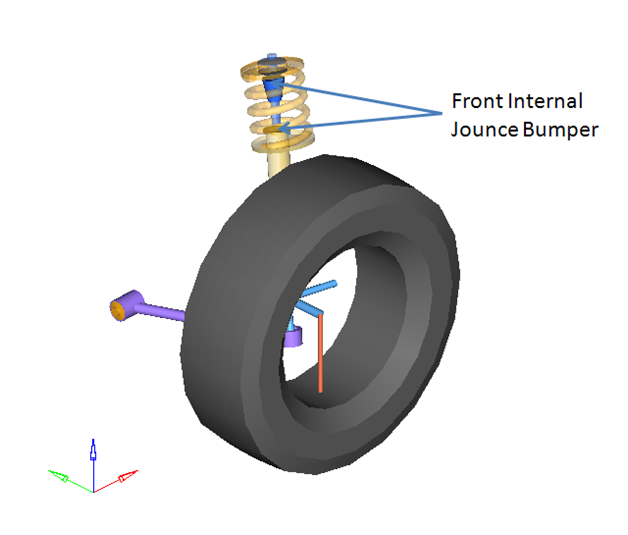
Front Internal Jounce Bumpers with Full Vehicle
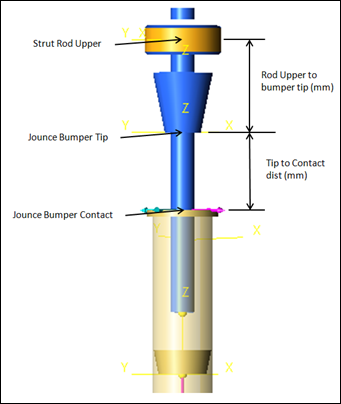
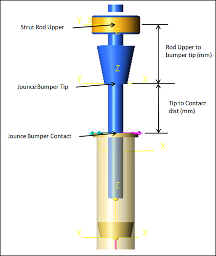
Jounce Bumper Points and Distances
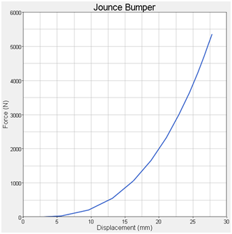
Jounce Bumper Force - Deflection Curve
Notes
| • | The Force element in the system uses an expression to turn on and off the jounce bumper when the tip reaches the contact. |
| • | Linear extrapolate is on by default in the jounce bumper curve. For robust simulations, make sure the force deflection curve values exceed the forces and deflections seen in the simulation. |
| • | The system uses calculated point locations to define the graphics and force locations. Markers (based on the points) are used in the Force expression. |
| • | The Force deflection curve of the Jounce bumper is 0,0 when the bumper just touches the contact point, and is a positive pair of points after contact. |
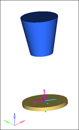
| • | The graphics are defined so the Jounce bumper graphic (represented by the cone) begins to pass through the contact plane graphic (a flat round plate) at the same time the jounce bumper force initiates. |
| • | The jounce bumper force acts at the “contact point” and is an action/reaction force which acts along the axis of the strut, or shock, between the strut/shock rod and the strut/shock tube bodies. |
| • | Damping is ignored, however it is able to be added. |
System Description
The entities in the analysis are displayed in the MotionView Project Browser as shown in the image below:
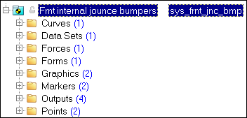
Project Browser View - Front Internal Jounce Bumper
Attachments determine how the system connects to the rest of the model. The Front Internal Jounce Bumper system includes four attachments (Rod Body, Tube Body, Upper Rod, and Lower Tube).
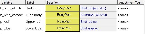
Front Internal Jounce Bumpers - Attachments
Attachment
|
Description
|
Rod Body
|
By default, the Rod Body attaches to the Strut rod (upper strut) in struts and to the Shock rod (upr shk) in shock absorbers. This is the first of the action/reaction Force bodies.
|
Tube Body
|
By default, the Tube Body attaches to the Strut tube (lower strut) on struts and to the Shock Tube (lwr shk) on shock absorbers. This is the second of the action/reaction Force bodies.
|
Upper Rod
|
By default, the Upper Rod attaches to the Point pair, Strut rod upper on struts, and the Shock Upr bush on shock absorbers. The Jounce bumper distances are defined from this point.
|
Lower Tube
|
By default, the Lower Tube attaches to the Point pair, Strut tube lower on struts, and Shock lwr bush on shock absorbers. The Lower Tube attachment and Upper Rod attachment points define the axis of the jounce bumper. Forces, graphics, and markers use this axis to define the Jounce bumper system.
|
|
The Front Internal Jounce Bumper system contains one option: Compliant. Setting this option to No will have no affect on the internal jounce bumper system entities.
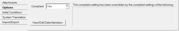
Front Internal Jounce Bumpers - Options
|
A single curve is included in the system (Jounce Bumper 1). The curve defines the Force-displacement behavior of the jounce bumper. The 0,0 point on the curve is when the bumper initially contacts the contact surface. Data should always be in the positive quadrant and should always increase in both the X and Y directions.
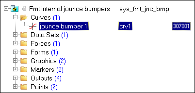
Project Browser View - Curves - Jounce Bumper 1
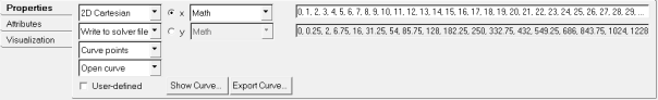
Curve Panel - Jounce Bumper 1
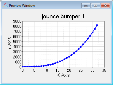
Preview Window Dialog - Jounce Bumper 1
|
One dataset (Jounce Bumper Lengths) is used in the system and contains dimensions that define the Jounce Bumper system. Two lengths define the graphics and forces of the jounce bumper. The Shock length is a calculated value.
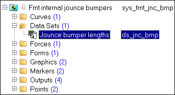
Project Browser View - Datasets - Jounce Bumpers Lengths
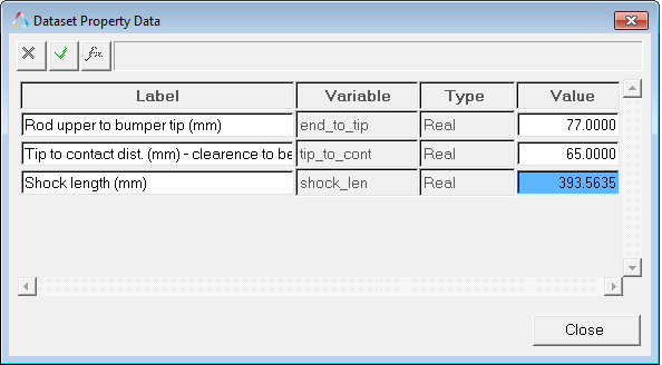
Dataset Property Dialog - Datasets - Jounce Bumper Lengths
Label
|
Description
|
Rod upper to bumper tip (mm)
|
Determines the coordinates of the jounce bumper tip PointPair.
|
Tip to contact dist. (mm) - clearance to be set manually in the curve x offset
|
Determines the coordinates of the jounce bumper contact PointPair.
|
Shock length (mm)
|
Parametric value that determines the PointPair co-ordinates for “jounce bumper tip” and “jounce bumper contact”.
It is of the form:
sqrt((p_rod.l.x-p_tube.l.x)^2+(p_rod.l.y-p_tube.l.y)^2+(p_rod.l.z-p_tube.l.z)^2)
|
Datasets - Jounce Bumpers Lengths
|
The Front Internal Jounce Bumper contains one force (Jounce Bumper). This is an action-reaction force that acts in the translational direction, between the Strut Tube and Strut Rod along the axis of the strut or shock absorber. The translational force properties are non-linear and are defined using a curve.
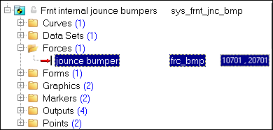
Project Browser View - Forces - Jounce Bumper
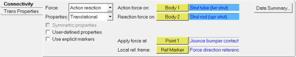
Jounce Bumper Panel
Principal Forces - Front Internal Jounce Bumper
|
One Form is used in the Front Internal Jounce Bumper system (Jounce Bumper Lengths). The Form is the only place where changes should be made to the Jounce Bumper length data. The two parameters that can be changed are: Rod upper to Bumper tip and Tip to contact distance.
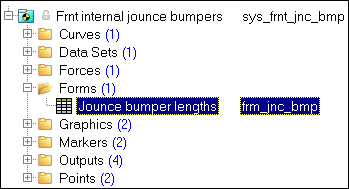
Project Browser View - Forms - Jounce Bumpers Lengths
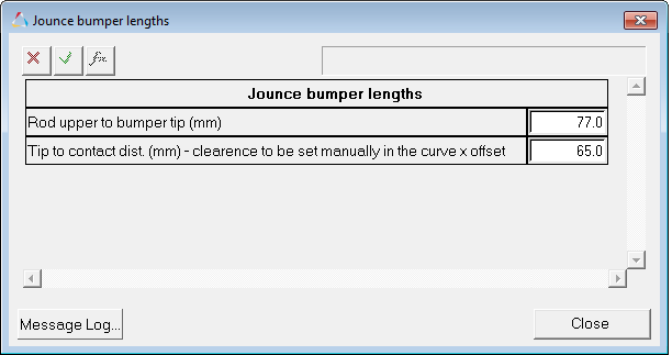
Jounce Bumper Lengths Dialog

Forms - Jounce Bumpers Lengths
|
Two Graphics are used in Front Internal Jounce Bumper (Jounce Bumper and Jounce Bumper Contact). The Jounce Bumper attaches to the Strut Rod (upper strut) and the Jounce Bumper Contact attaches to the Strut Tube (lower strut).
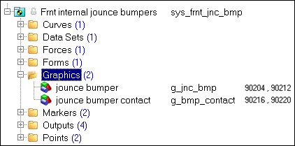
Project Browser View - Graphics - Front Internal Jounce Bumper
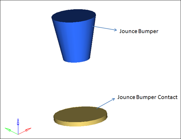
Jounce Bumper and Jounce Bumper Contact Graphics
|
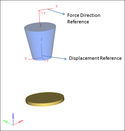
Two Markers that are symmetrical about XZ plane are used in the Front Internal Jounce Bumper system (Force Direction Reference and Displacement Reference).
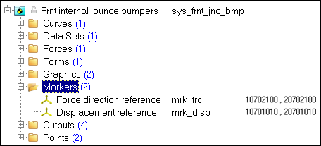
Project Browser View - Markers - Front Internal Jounce Bumpers
The force direction reference marker is located on the strut tube and the displacement reference marker is located on the strut rod. These markers are used define the location and direction for the Forces and Requests in the Jounce Bumper system.
Marker
|
Location Description
|
Use
|
Force Direction Reference
|
Origin is at the strut rod upper or shock upper bush.
Z axis points at the Jounce bumper contact
Attached to the Strut tube (lwr strut) or shock tube (lwr shk).
|
The jounce bumper force acts along the z axis of this marker.
The jounce bumper force request reports forces in this reference frame.
|
Displacement Reference
|
Origin is at the jounce bumper tip.
Z axis points at the Strut rod upr or shock upper bush.
Attached to the Strut rod (upr strut) or shock rod (upr shk).
|
The jounce bumper displacement request is measured in this coordinate frame.
The jounce bumper Force expression uses this marker in the equation to calculate force.
|
Markers - Front Internal Jounce Bumper
|
Four output requests are used in Front Internal Jounce Bumper system (Left Jounce Bumper Displacement, Right Jounce Bumper Displacement, Left Jounce Bumper Force, and Right Jounce Bumper Force). These four requests will generate eight sets of results.
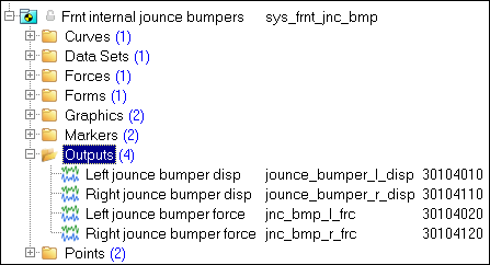
Project Browser View - Outputs - Front Internal Jounce Bumpers
Output
|
Description
|
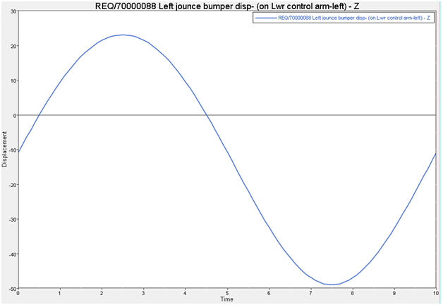
Left Jounce Bumper Displacement
|
Displacement of the jounce bumper on the left side of the vehicle. Displacement of the bumper contact relative to the bumper tip, and the displacement of the contact tip relative to the bumper contact are reported. Both requests are in the Displacement Marker reference frame.
|
Right Jounce Bumper Displacement
|
Displacement of the jounce bumper on the right side of the suspension. The contact tip relative to the bumper contact are reported. Both requests are in the Displacement Marker reference frame.
|
Left Jounce Bumper Force
|
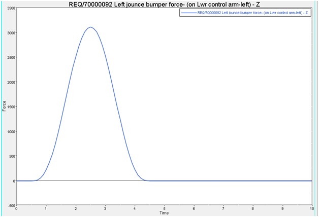
The Jounce bumper force on the left side suspension. The force pushes the bodies apart when the bumper is engaged. The force is reported on both parts of the force element, and the forces will be equal and opposite.
|
Right Jounce Bumper Force
|
The Jounce bumper force on the right side of the suspension. The force pushes the bodies apart when the bumper is engaged. The force is reported on both parts of the force element, and the forces will be equal and opposite.
|
An example of the jounce bumper displacement output is shown below:
An example plot of the jounce bumper Force output plot is shown below:
|
Two point pairs are used in the Front Internal Jounce Bumper system. These points are used to create the Jounce Bumper Tip and the Jounce Bumper Contact. The points contain parametric logic to define their X, Y, and Z locations. No user modification of any points should be necessary.
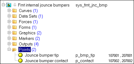
Project Browser View - Points - Front Internal Jounce Bumpers

Jounce Bumper Points and Dimensions
The table below shows the coordinate values for the Jounce Bumper Tip point when located internally:
Coordinate
|
Expression (Front-Left)
|
X
|
p_rod.l.x+(p_tube.l.x-p_rod.l.x)/ds_jnc_bmp.shock_len.value*ds_jnc_bmp.end_to_tip.value
|
Y
|
p_rod.l.y+(p_tube.l.y-p_rod.l.y)/ds_jnc_bmp.shock_len.value*ds_jnc_bmp.end_to_tip.value
|
Z
|
p_rod.l.z+(p_tube.l.z-p_rod.l.z)/ds_jnc_bmp.shock_len.value*ds_jnc_bmp.end_to_tip.value
|
The variables used in the above expression are described below:
Expression
|
Model Equivalent
|
p_rod.l.x
|
X coordinate of the Upper Rod Attachment Point – Left
|
p_tube.l.x
|
X coordinate of the Lower Tube Attachment Point – Left
|
p_rod.l.y
|
Y coordinate of the Upper Rod Attachment Point – Left
|
p_tube.l.y
|
Y coordinate of the Lower Tube Attachment Point – Left
|
p_rod.l.z
|
Z coordinate of the Upper Rod Attachment Point – Left
|
p_tube.l.z
|
Z coordinate of the Lower Tube Attachment Point – Left
|
ds_jnc_bmp.shock_len.value
|
Total shock length value defined in the dataset
|
ds_jnc_bmp.end_to_tip.value
|
Distance from the shock rod upper to bumper tip defined in the dataset
|
The table below shows the co-ordinate values for the Jounce Bumper Contact point when located internally:
Coordinate
|
Expression (Front-Left)
|
X
|
p_rod.l.x+(p_tube.l.x-p_rod.l.x)/ds_jnc_bmp.shock_len.value*(ds_jnc_bmp.end_to_tip.value+ds_jnc_bmp.tip_to_cont.value)
|
Y
|
p_rod.l.y+(p_tube.l.y-p_rod.l.y)/ds_jnc_bmp.shock_len.value*(ds_jnc_bmp.end_to_tip.value+ds_jnc_bmp.tip_to_cont.value)
|
Z
|
p_rod.l.z+(p_tube.l.z-p_rod.l.z)/ds_jnc_bmp.shock_len.value*(ds_jnc_bmp.end_to_tip.value+ds_jnc_bmp.tip_to_cont.value)
|
The variables used in the above expression are described below:
Expression
|
Model Equivalent
|
p_rod.l.x
|
X coordinate of the Upper Rod Attachment Point – Left
|
p_tube.l.x
|
X coordinate of the Lower Tube Attachment Point – Left
|
p_rod.l.y
|
Y coordinate of the Upper Rod Attachment Point – Left
|
p_tube.l.y
|
Y coordinate of the Lower Tube Attachment Point – Left
|
p_rod.l.z
|
Z coordinate of the Upper Rod Attachment Point – Left
|
p_tube.l.z
|
Z coordinate of the Lower Tube Attachment Point – Left
|
ds_jnc_bmp.shock_len.value
|
Total shock length value defined in the dataset
|
ds_jnc_bmp.end_to_tip.value
|
Distance from the shock rod upper to bumper tip defined in the dataset
|
ds_jnc_bmp.tip_to_cont.value
|
Distance from the bumper tip to bumper contact defined in the dataset
|
|
Similar Systems:
| • | Rear Internal Jounce Bumpers |
| • | Front Internal Rebound Bumpers |
| • | Rear Internal Rebound Bumpers |


