|
»Click here to display Table of Contents«
|

Flexbody Post-processing |

|

|

|

|
|
Flexbody Post-processing |
|
|
|

|
|
»Click here to display Table of Contents«
|
Flexbody Post-processing |
|
|
|
|
|
Flexbody Post-processing |
|
|
|
|
MotionView models solved in MotionSolve or Adams can be animated in Hyperview. In addition, the plots for these models can also be viewed in HyperGraph.
To view the animation of flexible body results generated using MotionSolve, the result H3D file must be loaded in HyperView:
| 1. | From the Select application menu, select HyperView |
See Opening Files in HWD for additional information.
| 3. | From the Load Model panel, verify that the Load model and Load results check boxes are activated. |
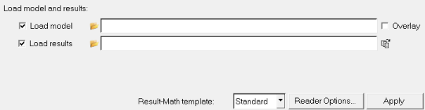
| 4. | Click the Load model file browser |
The Load Model File dialog is displayed.
| 5. | Open the .h3d result file. |
The same file is automatically loaded into the Load results field.
| 6. | Click Apply. |
HyperView supports post-processing of transient analyses and modal (ADAMS Linear) analyses of ADAMS simulations that contain flexbodies.
The following files are required to completely post-process an ADAMS flexbody:
| • | FLX (ASCII file) |
| • | GRA (rigid body graphics and results) |
| • | RES (ASCII of flexbody modal participation factors) |
| • | H3D #1 (first flexbody) |
| • | H3D #2 (second flexbody) |
| • | H3D #N (Nth flexbody) |
| Note | To view stresses or displacements on a flexbody model during animation solved using the ADAMS solver, the RES file should be requested. In absence of the RES file, the stresses in the ADAMS results will not be shown in the animation. Refer to the Solver Parameters section of the Exporting MDL Models to ADAMS topic for additional information. HyperView can only read the ASCII format of the ADAMS .res file. |
When MDL generates the ADAMS solver input deck, it also creates a FLX file. The FLX file is a small ASCII file that points to the files necessary for post-processing the ADAMS run corresponding to that MDL model. The path to the files is relative.
Commands supported in the FLX file include:
*ModelSource()
*ResultSource()
*FlexSource()
*AssignIdToVarname()
*AddObjectsFromFile()
*DefineColor()
*TempFileDirectory()
*SetAdamsDirectory()
*ModelSource(), *ResultSource(), and *FlexSource() assemble all necessary information for animation. *TempFileDirectory() allows you to define the directory to which scratch files are written.
A subset of the total time or total mode set can be animated using the following statements inside the FLX file. This allows all frames to be calculated at load time, without requiring all frames to be included in the calculation. For models containing large flexbodies, the reduced calculation time can reduce the initial load time. The following commands are valid for FLX files:
Command |
Description |
|---|---|
*ModelSource(string) |
Defines the source of the file containing rigid body graphics. |
*ResultSource(string) |
Defines the source of the file containing flexbody modal participation factors as well as rigid body time histories. |
*FlexSource(string, body_id, scale) |
Defines the source of the graphics for the flexbody as well as identifying the ID of the flexbody in the solver input deck and animation scale. Scale determines the magnification of the deformation of the flexbody and can be set independently for each flexbody. |
*AssignIdToVarname |
Matches an ADAMS varname with a MotionView ID. |
*AddObjectsFromFile |
Parses ADAMS CMD file and reads in all WaveFront objects. |
*DefineColor |
Defines a color used in the ADAMS CMD file. All default colors that exist when ADAMS is started do not need to be defined. |
*TempFileDirectory("string") |
Allows you to control which directory is used when MotionView creates scratch files during the processing of flexbody animations. |
*SetAdamsDirectory() |
For parasolid objects, use *SetAdamsDirectory() in the FLX file. While creating an H3D file for a parasolid, select Manual Mesh and activate the Place Elements on Surface Component option. |
| Note | You should briefly review the FLX file if it has been moved from one location to another to confirm relative paths. |
If Apply is not highlighted in HyperView's Load Model panel, one or more files in the FLX file cannot be located.
An example FLX file is shown below:
*ModelSource("double_link.gra")
*ResultSource("double_link.res")
*FlexSource("../h3d_flexbodies/link_flex.h3d", 1, 100000.0)
*FlexSource("../h3d_flexbodies/link_flex.h3d", 2, 10000.0)
*AssignIdToVarname(ges_chassis_BODY, 51)
*AddObjectsFromFile("u222_ltlc_full_sys_cnrd_1.cmd")
*DefineColor("ForestGreen", 52, 97, 254)
To animate the flexible body results and view contours in HyperView:
See Opening Files in HWD for additional information.
| 2. | From the Load Model panel, verify that the Load model and Load results check boxes are activated. |
| 3. | Click the Load model file browser |
The Load Model File dialog is displayed.
| 4. | Open the ALTAIR.flx file. |
The same file is automatically loaded into the Load results field.
| 5. | Click Apply. |
| 6. | Click the Start/Pause button |
| 7. | Click the Contour panel button |
The Contour panel is displayed.
| 8. | Use the Contour panel to view displacement or stress contours on the model. |