MotionView can write input decks for the Abaqus solver. Users can:
| • | Export Abaqus solver input deck (*.inp) for the rigid body model |
| • | Replace a rigid body in the model with a ABAQUS substructure (flexible body) and export ABAQUS solver input deck (*.inp) |
| • | Replace a rigid body with ABAQUS inp (nodal FE component) file and export ABAQUS solver input deck (*.inp) |
The results of the Abaqus solver can be post processed in HyperView.
Here is the flow of flexible body creation and integration:
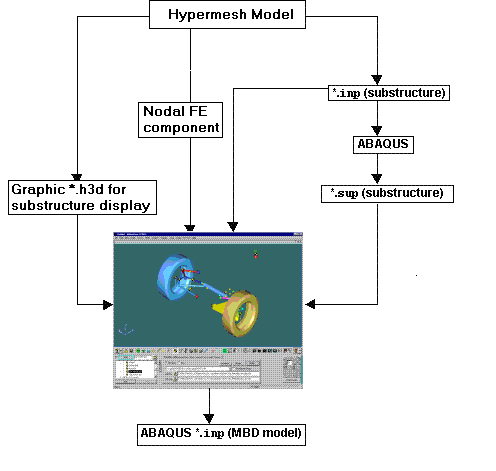
Integrating Abaqus substructure or FE model in MotionView
Exercise
In the first step of the exercise, you will be creating an Abaqus substructure. The second step involves the replacement of the rigid lower control arm with the Abaqus substructure. In the third step you will run the solver, and in last step you will post process the results.
Copy the folder abaqus, located in the mbd_modeling\externalcodes folder, to your <working directory>.
Step 1: Creating the Flexible Body Substructure.
First, you will need to create the flexible body. This stage must be completed in Abaqus, independent of MotionView.
It is assumed that you are familiar with flexible multi-body dynamics in Abaqus. Here is a brief overview of the steps you would need to do in Abaqus to generate a substructure:
| • | Use standard elements to define the structure |
| • | Assign material and geometric properties to the elements |
| • | Define the retained degrees of freedom. The retained nodes will connect the substructure to the rest of the model |
| • | Substructures must be created in one analysis and used in a subsequent analysis |
| • | The Abaqus *.inp deck of a substructure generation analysis should look something like this: |
*NODE...
*ELEMENT...
*MATERIAL...
*STEP
*FREQUENCY, EIGENSOL=LANCZOS
20
*BOUNDARY
RETAINED_NODES, 1, 6
*END STEP
*STEP
*SUBSTRUCTURE GENERATE
TYPE=z2, LIBRAYR=carm_right, MASS MATRIX=YES, OVERWRITE, RECOVERY MATRIX=YES
*RETAINED NODAL DOFS, SORTED=NO
RETAINED_NODESET,1,6
*RETAINED EIGENMODES, GENERATE
1,20,1
*END STEP
This is just a sample deck. For detailed syntax you may have to look up Abaqus documentation.
| Note | You have been provided with two inp files: carm_left.inp and carm_right.inp. Use these files to generate the two substructure files (*.sup) for the left and right lower control arms using Abaqus. These substructure files should be named as carm_left.sup and carm_right.sup respectively. |
The intermediate files (*.stt, *.mdl, *.prt) created by Abaqus during the substructure generation analysis are required for reference during the MBD system analysis. You will need to generate these files in Abaqus. The result files (*.mrf, *.odb) which are needed for the post-processing step of this tutorial are provided.
Once the substructure is generated you should be ready to integrate it in your MBD model.
Step 2: Integrating a Flexible Body into the MBD System.
Once you complete the substructure generation step in Abaqus, you should have the <substructure-name>.sup file. This .sup along with the original <substructure-name>.inp file will be used to integrate your flexible body into MotionView.
| 1. | Start a new MotionView session and load the file sla_abaqus.mdl, located in <working directory>. |
| 2. | Make sure that the SolverMode is ABAQUS. |
| 3. | From the Project Browser, under the Bodies folder select the Lwr control arm. |
| 4. | On the Properties tab for the LCA-Left, activate the Deformable check-box. |
| 5. | Click Yes in the question dialog. |
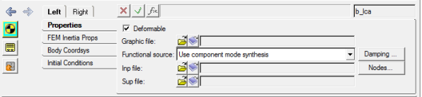
Notice that the graphics of the rigid body lower control arm vanishes.
Now you would need to specify a particular INP file that was used to create the flexible body.
| 6. | For Functional source, select the Use nodal FEA body option from the drop-down menu. |
| 7. | Using the Graphic file browser, select carm_left.h3d from your working directory. |
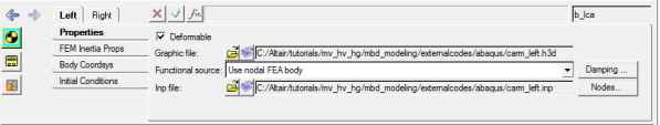
Properties tab
Notice that the Inp file field is automatically populated by MotionView.
| Note | The file carm_left.h3d is the graphic file for the ‘lower control arm-left’ body. This file is for display and assists in allowing faster pre-processing. The flexbody (or the INP file in this case) is used to provide data to the solver. The graphic H3D file can be generate from the input (INP) file (or CAD file) using the Import CAD or FE option located in the Tools menu in MotionView. In this exercise the graphic H3D files are provided. |
If the INP file is located in the same directory as the H3D graphic file, the Inp file field would be populated automatically. Otherwise, one also has the option of selecting the INP file from its respective location.
The Nodes dialog is displayed.
| 9. | Click the Find ALL button on the Nodes dialog to find nodes on the flexible body that are located closest to the interface points on the vehicle model. The vehicle model is attached to the flexible body at these interface nodes. |
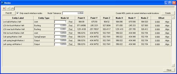
Nodes dialog
| Note | In this case there is no offset between the flexible-body interface nodes and their corresponding interface points on the vehicle model. But if there is an offset you can use the Align button. When you click the Align button, MotionView moves the connection point in the model to the node location on the flexible body. If the offset is more than the tolerance value, MotionView inserts a dummy body between the flexible body and the nearest connection point. This affects any other entities that reference this point. |
You can attach joints to the flexible body only at the interface nodes. These attachment nodes are created during your substructure generation analysis in Abaqus. Creating more attachment points increases the actual number of modes calculated, and may increase the CPU time.
| 10. | Close the Nodes dialog. |
| 11. | Repeat steps 6 through 9 to integrate the right side flexible body carm_right.inp in your model. |
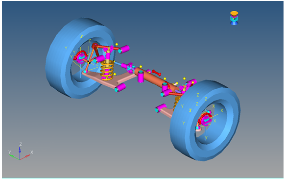
Your model should look like the image below:
| 13. | From the Tools menu, select Check Model to check your complete MBD model for errors. |
Step 3: Running MBD Systems in ABAQUS.
The flexible bodies are now fully integrated in your model. Now you will set up the ABAQUS solver run.
MotionView writes out the INP file for the whole MBD system. It is important that this INP deck should contain the substructure path references for the model to run successfully in Abaqus. The way to include these is via Templates in MotionView. Templex templates can be used to export syntax directly to the solver input deck, including parametric substitution if required.
| 1. | From the Project Browser, under the Templates folder select the Abaqus output template. |
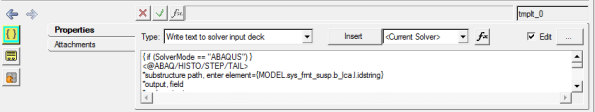
| 2. | Click the expansion button, , on the panel and read through the template. , on the panel and read through the template. |
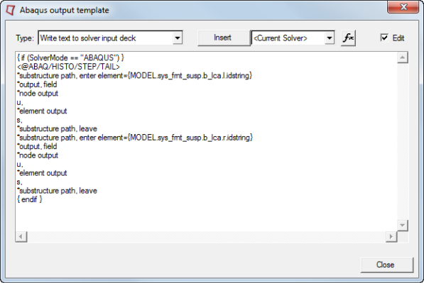
| Note | For the ABAQUS solver, the location of statements within the solver input deck is important. The four keywords used in this template allow you to position the extra text. These keywords must be the first line of the Templex template. For additional assistance and information on these keywords see the Exporting MDL models to ABAQUS topic in the online help. |
The remaining text of the template is written according to the position specified. In this case there are two substructure paths included for the two flexible bodies. You will need to add or delete such paths depending on the number of flexible bodies integrated in your model.
{MODEL.sys_frnt_susp.b_lca.l.idstring} is the parameterized path to grab the element ID number assigned to the left arm substructure.
Now your model is complete and ready to run in ABAQUS solver.
| 3. | Close the Abaqus output template. |
| 4. | From the Project Browser, under the Data Sets folder select ABAQUS Solution Options. |
| 5. | From the File menu, select Export > Solver Deck. |
| 6. | Save your model as an MDL file named sla_flex.mdl in the working directory. |
| 7. | Save your model as sla_flex.inp file in your working directory. |
| Note | You can run your model in ABAQUS at this stage. Select ABAQUS from the SolverMode menu and click on the Run icon on the toolbar to display the Run panel. Specify a file name for the inp file using the Save and run current model option and check the Export MDL animation file check box. Click on the Run button. MotionView will write the inp file and the maf file (which will be used for animation). If the ABAQUS solver script is linked to MotionView, the job will be submitted to ABAQUS. |
Step 4: Post-processing Abaqus Results.
You will now load the results of the Abaqus run in the Animation window.
| Note | MotionView has FIL2MRF translator residing in Tool..Custom wizards. Using this will allow you to translate an Abaqus fil file to an mrf file. In this exercise the mrf file is provided to you. |
The carm_left.odb and carm_right.odb files needed in this step will be generated once the model successfully runs in Abaqus.
| 1. | Click the Add Page icon,  , on the toolbar to add a new page to your session. , on the toolbar to add a new page to your session. |
| 2. | Select HyperView  from the Select window mode drop-down menu. from the Select window mode drop-down menu. |
| 3. | Load the sla_flex.maf and sla_flex.mrf as model and results files, respectively. |
| 4. | In the same window, again click the Load model file browser and select the carm_left.odb file from your working directory. |
| 5. | Activate the Overlay checkbox and click Apply. |
| 6. | Repeat the steps 4 and 5 to also overlay carm_right.odb file on the same model. |
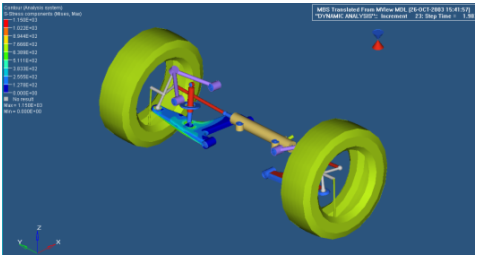
Notice that the substructures are overlayed on your model.
| 7. | Use the Entity Attributes panel,  , to turn off the graphics of the rigid control arm. , to turn off the graphics of the rigid control arm. |
| 8. | Click the Start/Pause Animation icon,  , on the Animation toolbar to animate the model. , on the Animation toolbar to animate the model. |
| 9. | Click the Start/Pause Animation icon again,  , to stop/pause the animation. , to stop/pause the animation. |


