FTire Integration with MotionView |

|

|

|

|
|
FTire Integration with MotionView |

|

|

|

|
Starting with MotionView 10.0-SA-110, you can create models directly within MotionView which are automatically set up to utilize tires. This can be done by making the following Assembly Wizard selections from the Model menu:
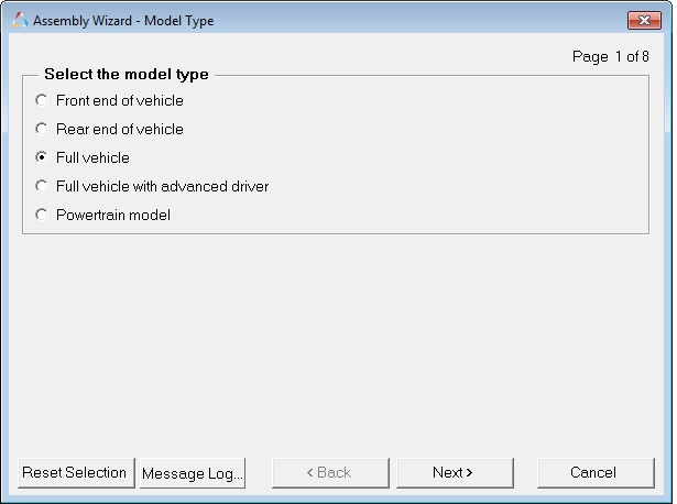
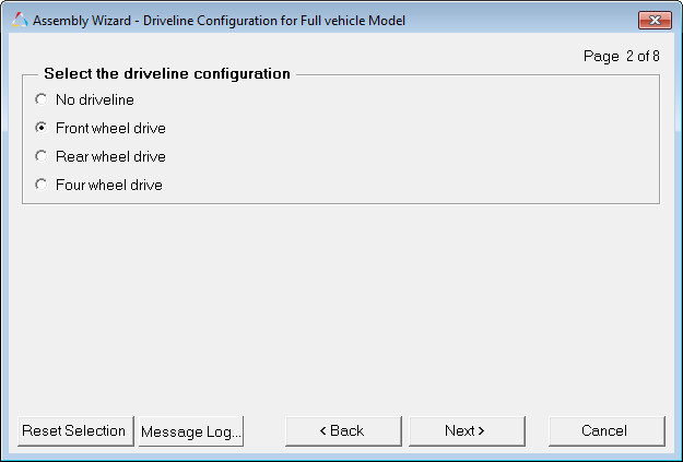
(or Rear wheel drive or Four wheel drive)
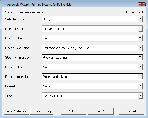
As long as FIALA/HTIRE is selected from the Tires drop-down menu, all other selections for the remainder of the Assembly Wizard will result in a full vehicle model enabled for tires.
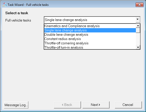
After this point, when the Task Wizard is selected from the Analysis menu, only full vehicle tasks will be available to select.
| Note | All full vehicle analyses will utilize tires. |
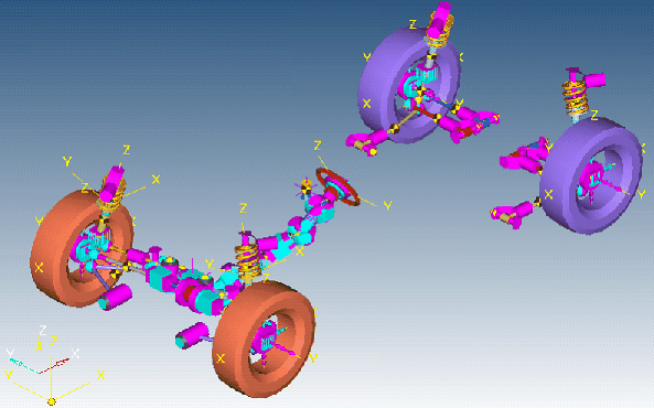
An example of a full vehicle model in MotionView is shown below:
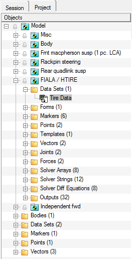
The resulting model will include an MDL system for the tires as shown in the browser image below (FIALA/HTIRE system):
The System panel will show all the necessary attachments for the HTIRE/FIALA tire system:

The six key attachments are:
| • | Wheel Center (Front & Rear): This is a Point entity used to define the location of the center of the wheel. |
| • | Spindle Alignment Point (Front & Rear): This is a Point entity used to define the spin axis of the wheel. |
| • | Wheel Body (Front & Rear): This is a Body entity used as the body where the tire forces are applied. |
Within this system is an MDL dataset called "Tire Data" which contains all the pertinent tire data, including references to the tire property file (.tir) and road property file (.rdf).
| Note | Each tire can use its own tire or road property file. |
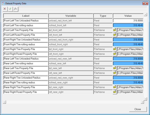
There is also a field for the unloaded radius, even though this same parameter is in the tire property file. The unloaded radius is used here to calculate the rolling radius (rolling radius is set to 98% of the unloaded radius). The rolling radius is used in turn to define the z location of the ground reference marker, thus defining the location of the road plane and ensuring that the road plane is slightly deforming the tire at the beginning of the simulation. It is important for you to keep the value of the unloaded radius in this table consistent with (equal to) the value used in the tire property file.
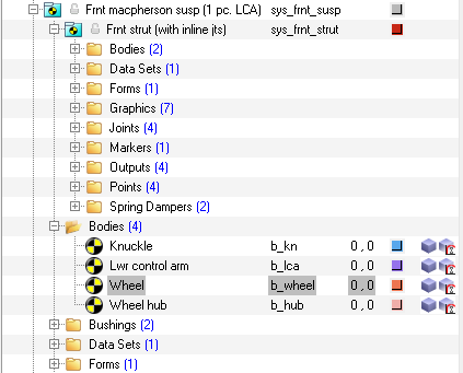
Wheel body parameters are found in the body panel for the wheel body (which is located under the Bodies folder in the corresponding suspension system).

See Also: