Why Flexible Bodies?
| • | Traditional multi-body dynamic (MBD) analyses involve the simulation of rigid body systems under the application of forces and/or motions. |
| • | In the real world, any continuous medium deforms under the application of force. Rigid body simulations do not capture such deformations and this may lead to inaccurate results. Inclusion of flexible bodies in MBD simulations accounts for flexibility. |
MotionView provides the modeling tools required to incorporate flexible bodies in your MBD model. Flexible MBD simulations allow you to:
| • | capture body deformation effects in simulations. |
| • | acquire greater accuracy in load predictions. |
| • | study stress distribution in the flexible body. |
| • | perform fatigue analysis. |
However, flexible bodies introduce an additional set of equations in the system and consequently, have a higher computational cost as compared to rigid body systems.
What is a Flexible Body?
| • | Finite element models have very high number of degrees of freedom. It is hard for MBD solvers to handle these. |
| • | A flexible body is a modal representation of a finite element model. The finite element model is reduced to very few modal degrees of freedom. |
| • | The nodal displacement in physical coordinates is represented as a linear combination of a small number of modal coordinates. |

where:
U
|
nodal displacements vector
|
Φ
|
modal matrix
|
Q
|
matrix of modal participation factors or modal coordinates to be determined by the MBD analysis.
|
| • | MotionView uses the process of Component Mode Synthesis(CMS) to reduce a finite element model to set of orthogonal mode shapes. |
Two types of CMS methods are supported in Optistruct:
| Note | At the end of this tutorial, links to online help direct you to where you can learn more about the theory behind flexible bodies and CMS method. |
Flexbody Generation Using Optistruct
There are two ways you can generate flexible bodies using Optistruct:
| 1. | Using the FlexPrep utility in MotionView. |
| 2. | Manually editing the input deck. |
Using the FlexPrep Utility in the MotionView Interface
FlexPrep is a MotionView utility which allows you to generate a flexible body from a finite element mesh. It also allows translation between various flexbody formats. These translations are discussed in the next section, "Flexbody Translation Using Flexprep".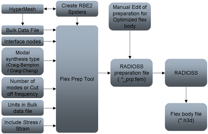
Using the FlexPrep GUI, you can:
| • | generate a flexible body from any Optistruct or Nastran bulk data file. |
| • | request for stresses and strains. |
| • | create Optistruct preparation file which can be used in the file size reduction of a flexible body. |
Manually Editing the Input Deck
You can manually insert certain cards in the Optistruct input deck to run the Component Mode Synthesis routine. These cards allow file size reduction of a flexbody. This helps in faster pre/post-processing and overall better efficiency of the process.
| Note | You can manually edit the preparation file generated by FlexPrep to reduce the size of the flexible body H3D. |
By modifying the input deck, you can:
| • | request only the skin elements of the flexbody to display . |
| • | request stress and strain information for a selected set of elements. |
| • | use released degrees of freedom for the interface nodes. |
The following data is included in a flexbody H3D file:
| 3. | Eigenvalues of all modes. |
| 4. | Inertia invariants (optional). |
| 6. | Nodal inertia (optional). |
|
| 7. | Translational displacement mode shapes. |
| 8. | Rotational displacement mode shapes. |
| 9. | Interface node IDs (optional). |
| 10. | Element stress/strain tensors (optional). |
| 11. | Global (rigid) inertia properties (optional). |
|
Flexprep.exe always generates points 1, 2, 3, 4, 5, 6, 7, 8, 9, and 11 and writes them to the H3D file. Points 4, 6, 9, and 11 are not strictly required.
Flexbody Translation Using FlexPrep
FlexPrep allows you to translate a flexbody from one format to another. Using FlexPrep, you can:
| 1. | Mirror an existing flexible body H3D file about a plane. |
| 2. | Translate an ADAMS MNF file to an Altair H3D file. |
| 3. | Translate an H3D file to an ADAMS MTX file. |
| 4. | Translate an Altair H3D file to ADAMS MNF file. |
| 5. | Translate an Nastran PCH file to an Altair H3D file. |
| 6. | Translate an Altair H3D file to DADS DFD file. |
| Note | Once the flexbody H3D is created, it can be used in the MBD model and the model can be submitted to either MotionSolve or ADAMS. This is covered in the following tutorials. |
Stress Recovery and Fatigue Calculations
Stress recovery and fatigue calculations are done in two stages during the MBD analysis:
| • | For stress recovery in the pre-processing stage, element stresses are obtained using the orthogonalized displacement modes. Every displacement mode is associated with a particular number of stress modes, each representing a basic stress tensor. This particular number depends on the type of elements used in the flexible body, for example, one, two, or three-dimensional elements. These stress modes are then saved to the H3D file. |
| • | In the post-processing stage, the actual stress recovery and fatigue index calculations are carried out. The modal participation factors obtained from the simulation are used to linearly superimpose the stress modes to come up with the stress tensor for each element. This stress tensor is used to calculate the other components of stresses: Principal, Shear, or von Mises. |
See also
Direct Matrix Input in the Optistruct User’s Guide for additional information regarding the Component Mode Synthesis theory.


