In this tutorial you will:
| • | get familiar with the flexible body generation techniques available in MotionView and Optistruct. |
| • | be introduced to all available features in FlexBodyPrep for flexbody generation. |
| • | be introduced to the various options available in Optistruct to reduce the size of the H3D file. |
There are two ways you can generate the flexible bodies for MBD simulation in Hyperworks:
| 1. | Using FlexPrep utility in MotionView interface. |
| 2. | Manually editing the input deck (*.fem) for Optistruct solver. |
Introduction to Flex Prep
Flex Prep is a tool in MotionView which is used to:
| • | create flexbody H3D files using Optistruct. |
| • | create flexbody H3D file from ADAMS MNF and NASTRAN PCH. |
| • | translate flexbody H3D file to ADAMS MTX, Altair H3D (mirrored), ADAMS MNF, DADS FDF, and nCode FES. |
Exercise: Creating and Simulating Flexible LCA
In this exercise, you will generate a flexible body for a left Lower Control Arm of a front SLA suspension. The input file is a pre-prepared .fem file (sla_flex_left.fem) which has finite element modeling information for the LCA (elements and nodes). Interface nodes for the flexible body are:
| • | the center nodes at the front and rear bushing mounts |
| • | location where the spring is attached |
| • | the center of the lower ball joint attaching to the knuckle. |
In the given input file, interface nodes are already created at the center of the bushing mounts and the spring attachment location. You will create the interface node at the lower ball joint and its connection to the LCA in the exercise.
Step 1: Using FlexBodyPrep.
Once you provide the required input, Flex Prep generates an input deck (_prp.fem) for the Optistruct solver with all the required cards, and then it calls Optistruct to run the job. Please refer to tutorial MV-2000 to understand all the inputs and process.
| Note | Copy the sla_flex_left.fem file, located in the mbd_modeling\flexbodies folder, to your working directory before proceeding further. |
| 1. | Open a new MotionView session. |
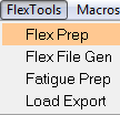
| 2. | From the Flex Tools menu, select Flex Prep. |
Launching Flex Prep
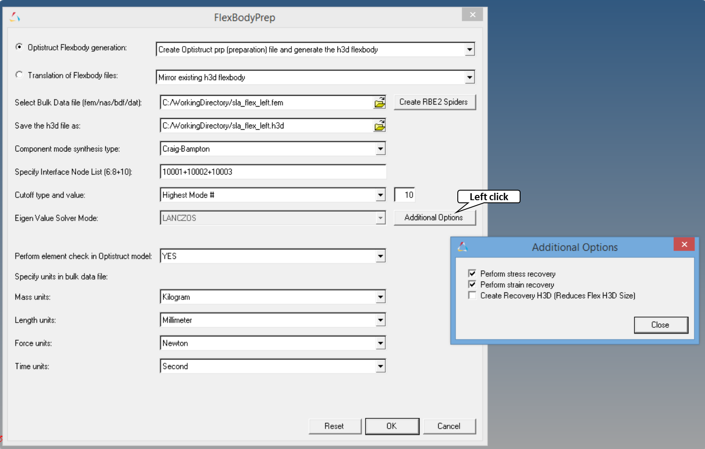
| 2. | Select Optistruct Flexbody generation. |
| 3. | From the pull down menu, pick the option Create Optistruct prp (preparation) file and generate the h3d flexbody. |
| 4. | Click on the file browser icon,  , next to Select Bulk Data file and select the input bulk data file sla_flex_left.fem from your working directory. , next to Select Bulk Data file and select the input bulk data file sla_flex_left.fem from your working directory. |
Note You can use any Optistruct (FEM) or Nastran (nas, dat, bdf) bulk data files.
| 5. | For Save the *.h3d file as, enter the name of the output H3D file as sla_flex_left.h3d in your <working directory>. |
| 6. | For the Component mode synthesis type, select Craig-Bampton to perform Craig-Bampton component mode synthesis. |
| 7. | In the Specify Interface Node List field, enter 10001+10002+10003. |
Note If the interface node IDs are within a range, you can specify as 10001:10003.
The interface nodes are the nodes where constraints or forces are applied in the MBD analysis.
| 8. | For the Cutoff type and value, select Highest Mode # and enter a value of 10. |
Limiting Modal Information
MotionView allows you to specify a limit on the modal information contained in your H3D file. Two methods are available to set these limits.
| - | Specify a maximum number of Eigen modes for which modal data is included in your H3D file. |
OR
| - | Specify an upper cut-off frequency for the Eigen modes. When a cut-off frequency is specified, normal modes analysis can be performed using one of two algorithms: Lanczos or the automated multi-level sub-structuring eigenvalue solution, AMSES. |
We used the first method in this exercise.
| a) | Click Additional Options to bring up the dialog. |
| o | Activate Perform stress recovery |
With this option set, Flex Prep puts relevant cards in the OptiStruct input deck to calculate the modal stresses while processing your bulk data file.
| o | Activate Perform strain recovery |
With this option set, Flex Prep puts relevant cards in the Optistruct input deck to calculate the modal strains while processing your bulk data file.
| Note | The Create Recovery H3D option is useful in fatigue analysis. A smaller flex H3D file is generated that contains the minimum amount of information required for MBD simulation in MotionSolve. A larger file, *_recov.h3d, is also generated that contains additional information for displacement, velocity, acceleration, stress, and strain. Refer to Recovering MBD Analysis Results in OptiStruct to learn more about using this method for fatigue analysis. |
FlexPrep utility with data
| 11. | Under Specify units in bulk data file, select the following: |
Mass Units
|
Kilogram
|
Length
|
Millimeter
|
Force
|
Newton
|
Time
|
Second
|
| Note | HyperMesh is unit-less and you need to make sure to use consistent units, or the flexbody generated will have incorrect modal frequencies. In the given input file, the density used is in unit kg/mm^3. Hence, you will use kilogram as the mass unit in this exercise. |
Generally, FE analysts using mm-N-sec as Length, Force and Time units need to specify mass as a derived unit as N-sec^2/mm (equivalent to tonne/mm^3/MEGAGRAMS). If the model that you use in the future may have such units, use MEGAGRAMS for the mass units in FlexBodyPrep.
| 12. | There are three RBE2 spiders already in sla_flex_left.fem. The fourth RBE2 spider should be created using the Create RBE2 Spiders option explained in the next step. |
Step 2: Create RBE2 Spiders.
If you have a circular hole in your finite element (FE) model and need to use the center of the hole as the interface node, you need to transfer the loads from the center node to the peripheral nodes. This feature allows to you create RBE2 spiders at the hole in the FE model to transfer forces from the interface node to peripheral nodes of the hole.
| Note: | If the finite element model definition is complete (all interface nodes and connections already exist), this step is not required. |
Description of an RBE2 Spider
An RBE2 is a rigid element whose independent degrees of freedom are specified at a single grid point and whose dependent degrees of freedom are specified at an arbitrary number of grid points. This is usually used to model relatively stiff connections.
| 1. | Click the Create RBE2 Spider button. |
| 2. | HyperMesh is invoked. The input file, sla_flex_left.fem, is imported into HyperMesh and the FE model is displayed in the graphics area of the screen. |
| Note | If HyperMesh asks for a user profile, click Cancel and go to the utility panel in the Browser area. |
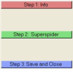
The Tab area displays a Utility tab with a user-defined page with three buttons (steps 1 to 3).
Note If the user defined page with the three buttons is not displayed, follow these steps to view it:
| - | From the View menu, select the Utility Menu. |
| - | From the Utility menu, click the User button, located at the bottom of the page. |
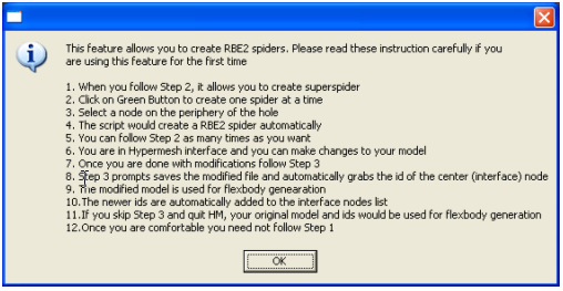
| 3. | The Info button details the procedure to create RBE2 spiders. |
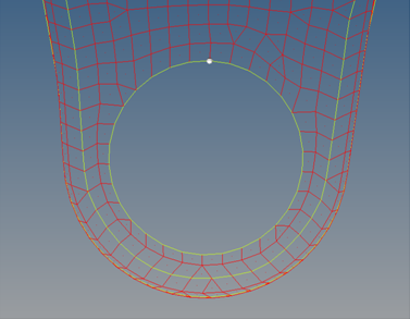
| 4. | Zoom into the area of the lower ball joint location as shown in the image below: |
| 5. | Click the Step 2: Superspider to create one spider at a time. |
| 6. | Select a node on the periphery of the hole and click Proceed. |
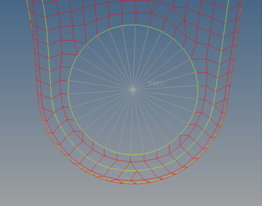
| 7. | The script would create a RBE2 Spider automatically as shown in image below: |
| 8. | Click the Step 3: Save and Close, which will save the modified file and automatically grab the ID of the center (interface) node. Give a new name to the file sla_flex_left_complete.fem and check to see if the interface node ID is added to the flex prep. |
| 9. | The new interface node IDs are automatically added to the interface node list in FlexBodyPrep as displayed in the image below: |
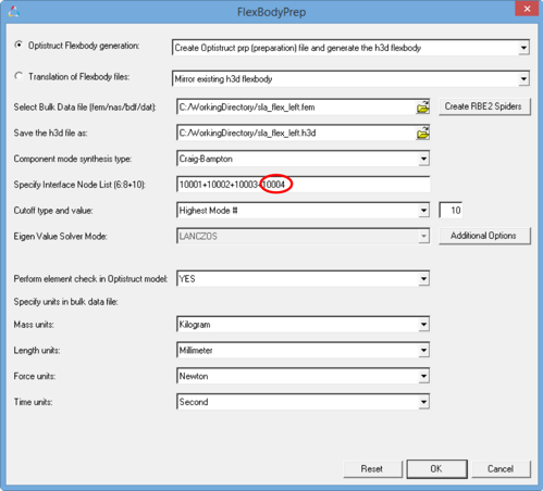
| 10. | Click OK to launch Optistruct in a command window. |
Based on the inputs provided here, FlexBodyPrep creates a new FEM file by appending _prp to the input filename and submits it to Optistruct. In this case, sla_flex_left_complete_prp.fem is created.
Messages from the FlexBodyPrep translator are displayed in the Output window. Check the status of the Optistruct run and look for any error messages there.
| 11. | Click OK in the Output window to close. |
Step 3: Viewing the model and verifying results.
In this exercise, you will verify your work in Step 1 by viewing the flexible control arm in HyperView.
| 1. | From Select window mode drop-down menu on the toolbar, select HyperView. |
The Load model and results: panel is displayed.
| 2. | Click the Load model file browser and select the H3D flex file, <working directory>/sla_flex_left.h3d. |
The flexible arm model and its modal results are contained in the H3D flex file you created using the Flexprep wizard.
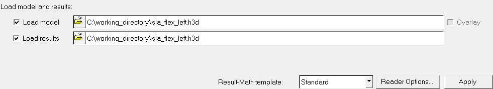
Load model and results fields
HyperView automatically updates the Load results file field with the same filename.
| 3. | Click Apply to load the model into the HyperView. |
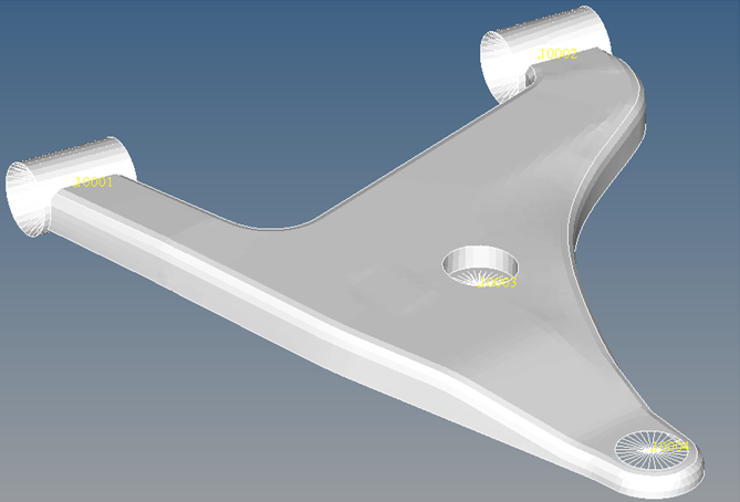
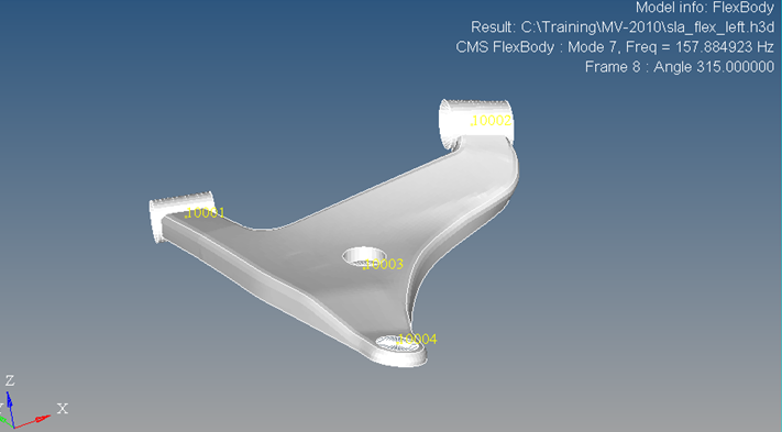
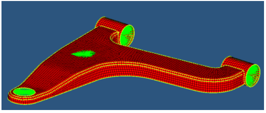
Flexible LCA Model
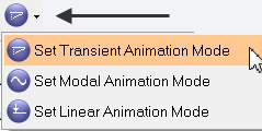
| 4. | Click the Select animation mode arrow and select Set Transient Animation Mode,  . . |
| 5. | Animate the results by clicking the Start Animation icon,  . . |
HyperView sequentially animates the flexible control arm through its mode shapes. The mode number and its frequency are displayed at the top-right of the window.
| 6. | Stop the cycling of modes by clicking the Pause Animation icon ,  . . |
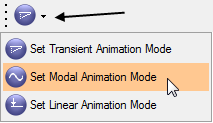
| 7. | Click the Select animation mode arrow and from the drop-down list, select Set Modal Animation Mode. |
| 8. | To animate a particular mode shape, go to the Results Browser and change the mode from Undeformed Model Frame to Mode 7. |
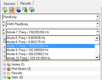
Selecting specific mode using the Simulation selector panel
| Note | Although there is not a direct correlation possible, you can recognize the first six modes as rigid body modes due to near zero frequency values. If there are more than six modes that are near zero, it generally indicates a model integrity problem (one or more elements are free and not connected to other elements). |
| 9. | Click the Animation icon, , to animate the selected mode. |
Toggle the animation on and off by clicking the button.
You can similarly animate other modes of the flexible body.
| 10. | Click the Contour button,  , to view the stresses on the flexbody. , to view the stresses on the flexbody. |
| 11. | From the Result type drop-down menu, select Stress and vonMises. For Entity with layers, select Z1 as shown in image below: |
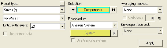
| 12. | Click Apply to display the contours and the legend in the graphic area. |
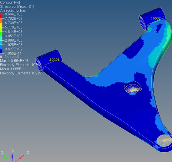
vonMises Stress contours displayed on the model
The above exercise demonstrated generating a flexible body using MotionView. Flexible bodies can also be generated by using Hypermesh and Optistruct. To learn more, you can refer to tutorial OS-1930 - Generating a Flexible Body for use in Altair MotionSolve.
Step 4: Invoking FlexPrep in batch mode.
The FlexPrep executable can also be invoked in batch mode.
To run the FlexPrep from the command line in LINUX or Mac:
<install_path>/altair/scripts/flexprep
To run the FlexPrep from the command line in DOS:
<install_path>\io\translators\bin\<os>\flexprep.exe (where <os> is either win32 or win64).
The usage options and corresponding syntax is listed if the above command is given without any arguments.
The sla_flex_left.h3d flexbody created in the earlier exercise is the lower control arm of a left front SLA suspension. Now, we will create a symmetric flexible body for the right front SLA suspension by invoking flex prep in batch mode.
| Note | In this exercise, you will run the FlexPrep translator from the MS DOS prompt for the Windows Operating System. You may follow analogous steps for the Linux/Mac OS terminal. |
| 1. | From the Start menu, open an MS DOS prompt window. |
| 2. | Use the cd command to navigate to your working directory. |
| 3. | Enter the command to launch FlexPrep <install_path>\translators\flexprep.exe. |
| 4. | Go through the usage options for running the FlexPrep translator in batch mode. |
| 5. | Enter the following command: |
<install_path>\io\translators\bin\<os>\flexprep.exe sla_flex_left.h3d sla_flex_right.h3d -MIRROR_XZ
| 6. | FlexPrep creates the mirrored lower control arm sla_flex_right.h3d flexbody file. |
Exercise: Manual Methods to Reduce the Size of the Flexbody
The previous exercise discussed flexbody generation using FlexPrep. It is possible to generate flexbodies directly from Optistruct by editing the input FEM file and adding the cards that invoke the flexbody generation from Optistruct. Steps 1 to 4 below discuss these cards in brief.
Understanding the Optistruct input file for flexbody generation
| 1. | Open the file sla_flex_left_complete_prp.fem in any text editor. |
| 2. | The first few lines of the FEM file are given below with explanation for each line: |
Line 1: SUBCASE 1
Line 2: OUTFILE, sla_flex_left
Line 3: CMSMETH 1
Line 4: STRESS=ALL
Line 5: STRAIN=ALL
Line 6: BEGIN BULK
Line 7: DTI, UNITS, 1, KG, N, MM, S
Line 8: PARAM COUPMASS -1
Line 9: PARAM CHECKEL YES
Line 10: CMSMETH, 1, CB, , 10
Line 11: ASET1, 123456, 10001
Line 12: ASET1, 123456, 10002
Line 13: ASET1, 123456, 10003
Line 14: ASET1, 123456, 10004
SET DATA FOLLOWS
BULK DATA FOLLOWS
A generalized input deck (FEM file) need the cards specified above to generate a flexbody from Optistruct. The definition of each line is as follows:
Line 1: SUBCASE – indicates the start of a new subcase definition.
Line 2: OUTFILE – used to specify a base name for the H3D file.
Line 3: CMSMETH – is the card defining the component mode synthesis solution method used to generate flexbodies in Optistruct.
Line 4: STRESS=ALL – use to specify that modal stresses are to be computed by Optistruct for all the elements in the model.
Line 5: STRAIN=ALL – use to specify that modal strain values are to be computed by Optistruct for all the elements in the model.
Line 6: BEGIN BULK – defines the start of FE entities in the model.
Line 7: DTI, UNITS – defines the units for the flexbody.
Line 8: PARAM COUPMASS -1 – defines values for parameters used by Optistruct for the generation of a flexbody. In this case, lumped mass matrix approach is used by Optistruct for eigenvalue analysis.
Line 9: PARAM CHECKEL YES – parameter to perform element quality check before running the job. Specifying NO makes the solver skip the element check. Elements with poor quality may lead to inaccurate results.
Line 10: CMSMETH CB 10 – component mode synthesis method selected is Craig Brampton and 10 modes are requested.
Lines 11 to 14: ASET1 – defines the boundary degrees of freedom for the interface nodes.
With these cards specified, Optistruct generates a flexbody H3D file. The flexbody size can be large based on the bulk data file, number of interface nodes, and modes and stress/strain details. It is possible to reduce the size by using any of following methods:
| • | MODEL Set – Reduces the model information that is used for graphical display. |
| • | STRESS/STRAIN Set – Reduces the number of elements on which stress or strain calculation is requested. |
| • | OUTLINE – Reduces the model information to display only boundary edges. |
| • | Reduced DOF – Reduces the number of DOF that contribute to the flexible body information. |
Modifying the Input Deck to Incorporate Stress/Strain Set, Model Set, Outline and Released DOF into the Flexbody
In finite element modeling, nodes or elements can be grouped together to form a SET. These groups can then be used in other modeling cards that can take the nodes and elements as inputs collectively. In flexible body generation, the need to incorporate these sets in the Optistruct input deck is:
| • | to reduce the size of the flexbody. |
| • | to help increase the speed of the multi-body pre-processing, simulation and animation. |
Step 1: Stress/strain set in Optistruct.
The cards STRESS and STRAIN specify the elements for which the stress and strain computations have to be carried out during flexbody generation. Use this card if you are interested in viewing stress results for the body in your analysis. If the objective of using a flexible body is to incorporate the flexibility of the body and not calculate stresses, then not using this card drastically reduces the size of the H3D.
Syntax of the STRESS and STRAIN cards:
STRESS=[setid|ALL|NONE]
STRAIN=[setid|ALL]
setid is the ID of the set of elements.
Alternatively, if ALL is specified, the stress/strain is calculated for all elements.
If NONE is specified, the stress is not calculated on any elements. (Not having the STRESS card has the same effect).
In the FEM file that is opened, you can observe SET cards defined for nodes (keyword GRID) and elements (keyword ELEM).
| 1. | Modify the cards STRESS=ALL and STRAIN=ALL as STRESS=5 and STRAIN=5, respectively. |
| 2. | Modify the OUTFILE to read as OUTFILE, sla_flex_left_stress_set. |
| 3. | Save the file as sla_flex_left_stress_set.fem and close the file. |
| 4. | Generate the flexbody using FlexBodyPrep. From the Optistruct Flexbody Generation drop-down menu, select the option Create h3d flexbody using pre-existing prp file. |
| Note | You can use Optistruct to generate the flexbody. To run Optistruct from the command prompt, type the following the working directory: <install>\hwsolvers\bin\win32\Optistruct.bat sla_left_stress_strain_set.fem. |
| 5. | Start a new MotionView session and change the window type to HyperView. |
| 6. | Load in the H3D file sla_flex_left_stress_set.h3d generated by Optistruct. |
| 7. | Go to the Contour panel to apply Stress and Strain contours. You will see that only a few elements display the contours. These are the elements that were pre-selected for stress and strain computations using the element set. |
Step 2: Model Set in Optistruct.
This card lets you control the display of elements of the flexbody in the H3D file while using the H3D file during pre- and post-processing in MotionView.
Syntax of the MODEL card:
MODEL=setid|PLOTEL
Where MODEL is the Optistruct card that determines the elements to be written to the result file (H3D). setid is the ID of set that defines the element displayed.
The PLOTEL option will be discussed further in this tutorial
| 1. | Open the FEM input deck sla_flex_left_stress_set.fem in a text editor. |
| 2. | Add the model card as MODEL=4 above the line STRESS=5. |
| 3. | Change the OUTFILE line to read as OUTFILE, sla_flex_left_model_set. |
| 4. | Save the file sla_flex_left_model_set.fem to your working directory and close the file. |
| 5. | Run the FEM deck in Optistruct or you generate the flexbody using FlexBodyPrep. From the Optistruct Flexbody Generation drop-down menu, select the option Create h3d flexbody using pre-existing prp file. |
| 6. | In HyperView, load the H3D file generated by Optistruct. |
You will see that only a part of the flexbody is displayed. Only those elements included in the set that is used with the MODEL card are displayed here.
Step 3: Outline feature using PLOTEL elements in Optistruct.
The size of the flexbody can be greatly reduced by using PLOTEL elements in the Optistruct input deck for flexbody generation. In case you would like only the edges of the flexbody to be displayed in MotionView, PLOTEL elements can be defined in the input deck and displayed using the MODEL card. PLOTEL is a one-dimensional dummy element for use in display. This element does not contribute any mass or stiffness to the part.
Syntax of the PLOTEL element:
Where PLOTEL is the element type, EID is the element ID, G1 and G2 are the nodes used to define the element. For example: PLOTEL 8786 4698 1702
The FEM file that you are working with already contain PLOTEL elements.
The procedure to incorporate the PLOTEL feature is briefly explained here:
| • | You can use the features option in HyperMesh to generate the PLOTEL elements of the feature edges of your model automatically. The features option is available on the Tool page in HyperMesh. |
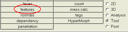
| • | The picture below shows a flexbody model with PLOTEL elements created with the features option: |
| • | Use the MODEL card and specify the PLOTEL option. |
MODEL=PLOTEL (to skip writing rigid elements like RBE2 as part of plotel, use optional keyword NORIGID)
| • | Save the FEM file and run it in Optistruct to generate the flexbody that displays only the PLOTEL elements. |
| 1. | Open the FEM deck sla_flex_left_model_set.fem, saved earlier in your working directory. |
| 2. | Replace the MODEL=4 by MODEL=PLOTEL. |
Within the BULK DATA, you will be able to see the many PLOTEL elements.
| 3. | Change the OUTFILE line to read as OUTFILE, sla_flex_left_plotel_set. |
| 4. | Save the file as sla_flex_left_plotel_set.fem. |
| 5. | Run the FEM deck in Optistruct or you can generate the flexbody from FlexPrep. From the Optistruct Flexbody Generation drop-down menu, select the option Create h3d flexbody using pre-existing prp file. |
| 6. | In HyperView, load the H3D file generated by Optistruct. |
You will see that the flexbody is shown only as lines or edges defined by the PLOTEL elements
Step 4: Released DOF method for interface nodes in Optistruct.
The released DOF (degrees of freedom) feature enables you to free some degrees of freedom of the interface nodes. If the appropriate DOF (corresponding DOF that are free in the MBD model) are released for a particular interface node, the simulation is not affected in any way. Depending on the kind of kinematic constraints in the model and the MBD simulation being carried out, you can release the appropriate degrees of freedom at the interface nodes to reduce the size of the H3D file generated.
The ASET1 card is used define the boundary degrees of freedom of an interface node of a flexbody.
Syntax of the ASET1 card:
ASET1 C
|
G1 or ASET1, C, G1
|
Where ASET1 is the card name, C is the DOF to be constrained, and G1 is the node ID. For example:
ASET1, 123456, 4927
This means that the interface node of ID 4927 will be constrained for all DOF, where 123456 represents the three translational and three rotational nodes in that order. Thus, to release a DOF from the interface node (for example, rotation about X), the C value will be 12356.
| 1. | Modify the ASET1 card corresponding to interface node 10004 in the deck as follows: |
ASET1, 123, 10004
| 2. | Change OUTFILE to read as OUTFILE, sla_flex_left_rdof. |
| 3. | Save the file in your working directory as sla_flex_left_rdof.fem and close the file. |
| 4. | Run the FEM deck in Optistruct or generate the flexbody from FlexPrep. From the Optistruct Flexbody generation drop-down menu, select the option Create h3d flexbody using pre-existing prp file. |
| 5. | Check the size of the H3D file generated and you will notice a reduction in size; this is due to the released DOF incorporated into the flexbody. |
Compare the sizes of all the H3D files generated using the cards mentioned in this step to know the reduction in file size.


