This document describes how to generate a dynamic link library (DLL) using Simulink Coder (formerly Real-Time Workshop) and link it with MotionSolve to run a co-simulation.
Pre-requisites:
| 1. | A working installation of MotionSolve (v12 and above) |
| 2. | A working installation of MATLAB, Simulink, MATLAB Coder, and Simulink Coder |
| 3. | A working installation of Microsoft Visual Studio (MSVS) 2010 |
Check for supported versions of MATLAB and MSVS here:
Supported Versions - Third Party Software in the XML Format Reference Guide.
This example uses MATLAB R2011b with MSVS 2010.
Step 1: Prepare the MotionSolve Model
The MotionSolve model is set up to communicate with an external solver by using the modeling statements Control_PlantInput and Control_PlantOutput:
<Control_PlantInput
id = "30100100"
num_element = "2"
variable_id_list = "30100400, 30100500"
sampling_period = "0.01"
offset_time = "0.0"
label = "for controller 1"
usrsub_param_string = "USER(987654321)"
usrsub_dll_name = "rtw_BusSuspension2PMIMODiscrete"
usrsub_fnc_name = "PINSUB"
hold_order = "2"
/>
<Control_PlantOutput
id = "30100200"
num_element = "2"
variable_id_list = "30100200, 30100300"
sampling_period = "0.01"
offset_time = "0.0"
label = "for controller 1"
usrsub_param_string = "USER(987654321)"
usrsub_dll_name = "rtw_BusSuspension2PMIMODiscrete"
usrsub_fnc_name = "POUTSUB"
hold_order = "2"
/>
<Control_PlantInput
id = "30100300"
num_element = "2"
variable_id_list = "30100800, 30100900"
sampling_period = "0.01"
offset_time = "0.0"
label = "for controller 2"
usrsub_param_string = "USER(987654321)"
usrsub_dll_name = "rtw_BusSuspension2PMIMODiscrete"
usrsub_fnc_name = "PINSUB"
hold_order = "2"
/>
<Control_PlantOutput
id = "30100400"
num_element = "2"
variable_id_list = "30100600, 30100700"
sampling_period = "0.01"
offset_time = "0.0"
label = "for controller 2"
usrsub_param_string = "USER(987654321)"
usrsub_dll_name = "rtw_BusSuspension2PMIMODiscrete"
usrsub_fnc_name = "POUTSUB"
hold_order = "2"
/>
The key attributes of Control_PlantInput and Control_PlantOutput needed to link a Simulink Coder DLL are listed below.
Attribute
|
Description
|
usrsub_param_string
|
Set this parameter equal to "USER(id)", where the ID is an integer (for example, 123) that you choose. The ID identifies the Simulink Coder library, links all Control_PlantInput's and Control_PlantOutput's that use the library, and must be unique.
Note: There can be more than one Control_PlantInput/Control_PlantOutput per library.
|
usrsub_dll_name
|
The name of the DLL that is used (for example, from Simulink Coder).
|
usrsub_fnc_name
|
The name of the user function/subroutine that MotionSolve calls. This has to necessarily be "PINSUB" for Control_PlantInput and "POUTSUB" for Control_PlantOutput.
|
In this case, this MotionSolve model has been prepared for you. Copy the MotionSolve and Simulink models, rtw_BusSuspension2PMIMODiscrete.xml and rtw_BusSuspension2PMIMODiscrete.mdl, located in the motionsolve\cosimulation folder to your <working directory>.
Step 2: Preparing the Simulink Model – Generating Code
Before starting with the simulation, the Simulink model needs to be created and prepared to work with MotionSolve. After generating the contents of the Simulink model, MotionSolve requires the Simulink components Inport and Outport, which represent the interface to the MotionSolve model. For example, like the following (blocks labeled below as In1, In2, Out1, Out2):
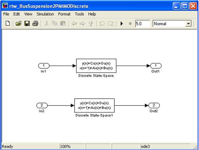
| Note: | If you have multiple inports/outports, you must retain the above illustrated naming scheme. All your inports must be defined as In1, In2, …, Inx. Similarly, all your outports must be named as Out1, Out2, …, Outx. This is a limitation within the current co-simulation framework and will be addressed in a future release. See Appendix B for more information. |
The order of these Inport's and Outport's must match the order of the Control_PlantOutput’s and Control_PlantInput's, respectively, in the MotionSolve model.
| 1. | Open rtw_BusSuspension2PMIMODiscrete.mdl in Simulink. |
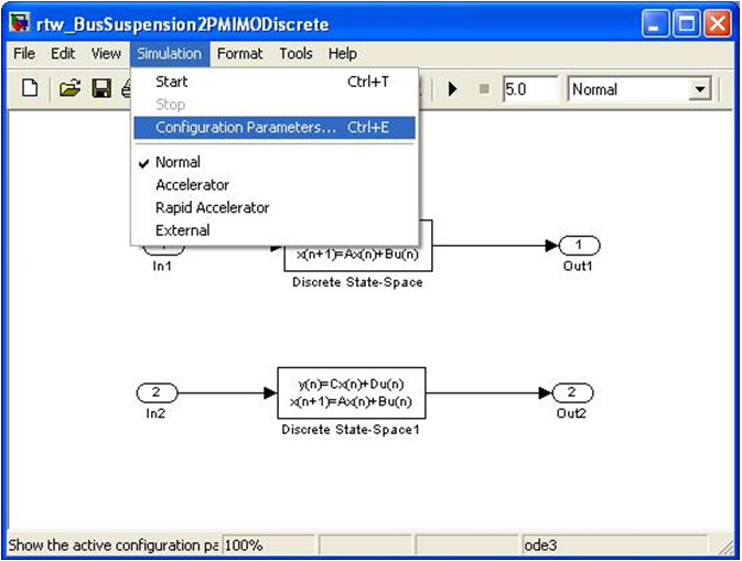
| 2. | Specify the configuration parameters in the solver, which is used by Simulink Coder. To do this, use the Simulation > Configuration Parameters… menu option as shown below. |
| 3. | In the left-side browser/tree, select the Code Generation option: |
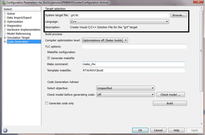
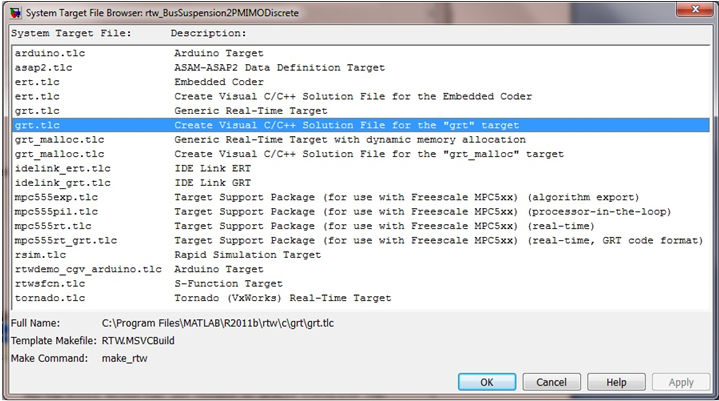
| 4. | Here, change the System target file by clicking Browse… and search for “grt.tlc – Create Visual C/C++ Solution File for the “grt” target”. This is shown below: |
| 5. | Once this is done, change the Language option to “C++” in this same Code Generation window. |
| 6. | Next, in the left-side browser/tree, select the Solver option: |
Simulink Coder does not allow using a variable-step integrator for the Generic Real-Time target that is required by MotionSolve to generate this code (more details on selecting the Generic Real-Time target later in this tutorial). So, under the Solver option on the left, choose the Fixed-step solver, as shown below:
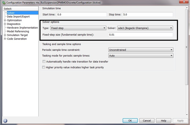
| Note | See the Mathworks documentation for more details on selecting an appropriate fixed-step size for your model (in particular, if the model has multiple sample times, you will likely need to choose a step size equal to the least common denominator of the specified sample times so that each sample time is hit by the solver). |
| 7. | Next, in the left-side browser/tree, select the Code Generation option again. |
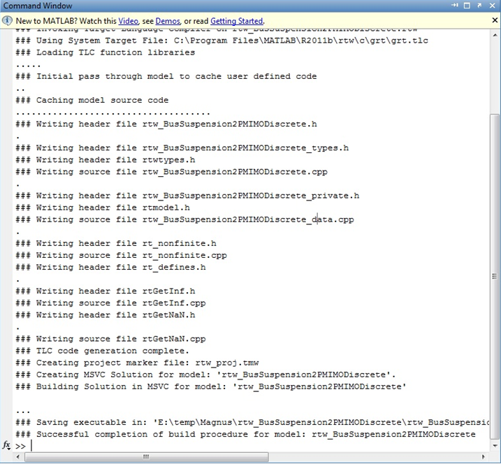
| 8. | Click on Build to build the code. The code generation creates two folders in the current directory of MATLAB (here <Simulink_model> is the name of the model): |
| • | <Simulink_model>_grt_rtw |
You should see messages that look similar to those below and end with:
### Successful completion of Real-Time Workshop build procedure for model: rtw_BusSuspension2PMIMODiscrete
…or similar.
Step 3: Modifying, Compiling and Linking the Code to Create the DLL
At this point, Simulink Coder has generated source code for the Simulink model, but this must be modified and recompiled to generate the DLL required by MotionSolve. In the next steps, you will use a script to automatically compile and link this code and generate the Simulink Coder DLL that will be used in the MotionSolve model.
| 1. | Open a command prompt in your working directory (where Simulink has generated the code). |
| 2. | Issue the following command: |
“ms_rtw_pre <mdl_name> <altair_root> <msvs_root> <win32|win64>”
where,
<mdl_name> is the name of the Simulink model (without the extension .mdl)
<altair_root> is the complete path to the root folder of the HyperWorks installation
<msvs_root> is the complete path to the root folder of the MSVS installation
<win32|win64> specify win32 or win64 depending on the required platform of the DLL
Notes:
| 1. | To successfully issue the ms_rtw_pre command, please include the path of the MotionSolve binaries in the “PATH” environment variable. This can be done locally by issuing the following command on Windows: |
set PATH = <MS_bin_path>;%PATH%
where <MS_bin_path> is the path to the MotionSolve binaries; for example, “C:\Program Files\Altair\13.0\hwsolvers\motionsolve\bin\win64”
| 2. | If the path to <altair_root> and/or <msvs_root> contains spaces, make sure to enclose the path in quotes. |
An example of the above command for this model is:
ms_rtw_pre rtw_BusSuspension2PMIMODiscrete "C:\Program Files\Altair\13.0" "C:\Program Files (x86)\Microsoft Visual Studio 10.0" "win64"
Issuing the above command does the following:
| • | Automatically modifies the project settings and source files of the original solution generated by Simulink Coder |
| • | Compiles and links the source code to generate a DLL that can be used with MotionSolve |
You can confirm that this process has completed successfully by looking at the output in the command window. On successful execution, you should see something like the following:
========== Build: 1 succeeded, 0 failed, 0 up-to-date, 0 skipped ==========
1 file(s) copied.
** RTW dll is ready **
Step 4: Run a MotionSolve Model with The Generated DLL
At this point, you simply need to point MotionSolve to the Simulink library to complete the co-simulation. By default, it assumes that it is in the same directory as the MotionSolve model.
| 1. | In this example, the ms_pre_rtw script should have created the generated DLL into the same folder where the MotionSolve model (.xml) resides. If the DLL is created elsewhere, copy it to the working directory of the MotionSolve .xml file. |
| 2. | Open a command window and change the path into this folder in order to run the model. |
| 3. | You will be running the MotionSolve model on command line, so certain environment variables must be set to be able to invoke MotionSolve. See the MotionSolve User’s Guide for more details on the options to run on the command line. |
| 4. | Run the MotionSolve model in the command line by issuing the command “mbd_d x.xml x.mrf”. |
The simulation should run quickly and you should review your results to confirm that the process worked as expected.
Appendix A
This section discusses the access functions CoSimAPI_SimulinkRTW_Update_U(api,model,input) and CoSimAPI_SimulinkRTW_Update_Y(api,model,output). These are added to the Simulink model source code in order to help perform the co-simulation via the DLL.
CoSimAPI_SimulinkRTW_Update_U(void *api, const RT_MODEL_x x_M, ExternalInputs_x &x_U)
This method updates the input data structure in the Simulink Coder generated code with the output from MotionSolve.
The first argument requests a pointer to the API ID. The API ID is passed from the model XML in the line usrsub_param_string = "USER(987654320)". The first parameter in the USER() string is always the ID of the API. The MotionSolve API provides the method void * CoSimAPI_Get_API_Ptr(int api_id) to get the API pointer, where the api_id is the number specified in the XML file in the USER() string.
The second argument requests data structure x_M related to the generated Simulink Coder model information where ‘x’ is the name of the model. The x_M data structure is inherent to the Simulink code.
The last argument requests input x_U where x_U is the data structure used by the Simulink Coder code to store the external inputs (see Appendix B).
CoSimAPI_SimulinkRTW_Update_Y(void *api, const RT_MODEL_x x_M, const ExternalOutputs_x x_y)
This method updates the input for the MotionSolve solver with output from the RTW generated code.
The first and second arguments are the same as described in the previous section.
The last argument requests RTW output x_Y which is deposited to MotionSolve for that current time step, where x_Y is the data structure used by the Simulink Coder code to store the external outputs (see Appendix B).
Appendix B
This section describes the data structure that Simulink Coder generated code uses for representing the external input/output ports. In the following lines, the name of the model is assumed to be rtw_MS (rtw = Real Time Workshop, former name of Simulink Coder).
Typically, the Simulink Coder generated code (SCGC) uses the following notations:
Input port to Simulink with single channel
|
rtw_MS_U.In1, rtw_MS_U.In2 etc.
|
Output port from Simulink with single channel
|
rtw_MS_Y.Out1, rtw_MS_Y.Out2 etc.
|
Input port with multiple channels
|
rtw_MS_U.In1[0], rtw_MS_U.In1[1] etc.
|
Output port with multiple channels
|
rtw_MS_Y.Out1[0], rtw_MS_Y.Out1[1] etc.
|
So for example, for a model with two Control_PlantInput (CPI) elements where the first has three channels and the second has two channels, the corresponding data structure in Simulink Coder code would be:
CPI #1: rtw_MS_U.In1[0], rtw_MS_U.In1[1] and rtw_MS_U.In1[2]
CPI #2: rtw_MS_U.In2[0] and rtw_MS_U.In2[1]
The same scheme is applicable for the data structure that handles Control_PlantOutput ports.
| Note | If the Simulink model has labels defined for the input/output links, then these labels will replace “In” and “Out” in the data structure described above. “In” and “Out” are the default names used by Simulink in case the links are not named. In this scenario, you need to change the first input variable name specified in the rtw api function template CoSimAPI_SimulinkRTW_Update_U(api,model,input) into the one you specified. |
For example, if you name the first input to be myIn instead of In1, you need to make the following change to that function template:
double *u_ptr = (double *)&u.myIn;
to replace the original code:
double *u_ptr = (double *)&u.In1;


