In this tutorial, you will learn how to:
| • | Model a PTCV (point-to-curve) joint |
A PTCV (point-to-curve) joint is a higher pair constraint. This constraint restricts a specified point on a body to move along a specified curve on another body. The curve may be open or closed, planar or in 3-d space. The point may belong to a rigid, flexible or point body. This constraint can help avoid modeling contact in some systems. It may prove advantageous since proper contact modeling (refer tutorial MV-1010) in many cases involves fine-tuning of contact parameters. One good example for such a system is a knife-edge cam follower mechanism. One can avoid modeling the contact between the cam and follower by defining a PTCV joint: the curve being the cam profile and the point being the tip of the follower.
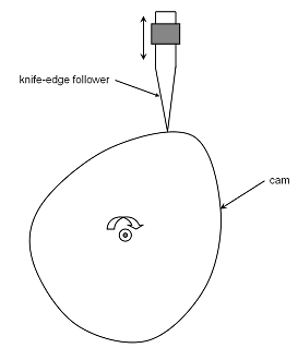
A Knife-edge Cam Follower Mechanism
In this tutorial, we will model a knife-edge cam follower mechanism with the help of a PTCV joint.
Exercise
Copy all the files from the mbd_modeling\interactive folder to your <Working directory>.
Step 1: Creating Points.
Let’s start with creating points that will help us locate the bodies and joints as required. We will define points for center of mass of the bodies and joint locations.
| 1. | Start a new MotionView Session. We will work with the default units (kg, mm, s, N). |
| 2. | From the Project Browser right-click on Model and select Add Reference Entity > Point (or right-click the Points icon  on the Model-Reference toolbar). on the Model-Reference toolbar). |
The Add Point or PointPair dialog is displayed.
| 3. | For Label, enter PivotPoint. |
| 4. | Accept the default Variable name and click OK. |
| 5. | Click on the Properties tab and specify the coordinates as X = 0.0 , Y = 0.0, and Z = 0.0. |
| 6. | Follow the same procedure and create the points specified in the following table: |
Point
|
X
|
Y
|
Z
|
FollowerCM
|
0.0
|
65.557
|
0.0
|
FollowerPoint
|
0.0
|
25.0
|
0.0
|
FollowerJoint
|
0.0
|
85.0
|
0.0
|
CamCM
|
0.0
|
-14.1604
|
0.0
|
Step 2: Creating Bodies.
We will have two bodies apart from the ground body in our model visualization; the cam and the follower. Pre-specified inertia properties will be used to define the bodies.
| 1. | From the Project Browser right-click on Model and select Add Reference Entity > Body (or right-click the Body icon  on the Model-Reference toolbar). on the Model-Reference toolbar). |
The Add Body or BodyPair dialog is displayed.
| 2. | For Label, enter Cam and click OK. |
| 3. | From the Project Browser right-click on Model and select Add Reference Entity > Body (or right-click the Body icon on the Model-Reference toolbar). |
The Add Body or BodyPair dialog is displayed.
| 4. | For Label, enter Follower and click OK. |
| 5. | From the Properties tab, specify the following for the two bodies: |
Body
|
Mass
|
Ixx
|
Iyy
|
Izz
|
Ixy
|
Iyz
|
Izx
|
Cam
|
0.174526
|
60.3623
|
63.699
|
123.276
|
0.0
|
0.0
|
0.0
|
Follower
|
0.0228149
|
7.10381
|
0.219116
|
7.22026
|
0.0
|
0.0
|
0.0
|
| 6. | For the Cam body, under the CM Coordinates tab, check the Use center of mass coordinate system box. |
The Select a Point dialog is displayed. Choose CamCM and click OK.
| 8. | Accept defaults for axes orientation properties. |
| 9. | For the Follower body, under the CM Coordinates tab, check the Use CM Coordsys box. |
| 10. | Double click on Point. |
The Select a Point dialog is displayed. Choose FollowerCM and click OK.
| 11. | Accept defaults for axes orientation properties. |
Step 3: Creating Joints.
Here, we will define all the necessary joints except the PTCV joint which will be defined as an advanced joint later. We require two joints for the model. The first of them is the revolute joint between the cam and ground body. The second joint we need is a translational joint between the follower and ground body.
| 1. | From the Project Browser right-click on Model and select Add Constraint > Joint (or right-click the Joints icon  on the Model-Constraint toolbar). on the Model-Constraint toolbar). |
The Add Joint or JointPair dialog is displayed.
| 2. | For Label, enter CamPivot. |
| 3. | Select Revolute Joint as the Type and click OK. |
| 4. | From the Connectivity tab, double-click on Body 1. |
The Select a Body dialog is displayed. Choose Cam and click OK.
| 5. | From the Connectivity tab, double-click on Body 2. |
The Select a Body dialog is displayed. Choose Ground Body and click OK.
| 6. | From the Connectivity tab, double-click on Point. |
The Select a Point dialog is displayed. Choose PivotPoint and click OK.
| 7. | For Axis click on the arrow and choose Vector. Now click on Vector. |
The Select a Vector dialog is displayed. Choose Global Z and click OK.
| 8. | From the Project Browser right-click on Model and select Add Constraint > Joint (or right-click the Joints icon on the Model-Constraint toolbar). |
The Add Joint or JointPair dialog is displayed.
| 9. | For Label, enter FollowerJoint. |
| 10. | Select Translational Joint as the Type and click OK. |
| 11. | From the Connectivity tab, double-click on Body 1. |
The Select a Body dialog is displayed. Choose Follower and click OK.
| 12. | From the Connectivity tab, double-click on Body 2. |
The Select a Body dialog is displayed. Choose Ground Body and click OK.
| 13. | From the Connectivity tab, double-click on Point. |
The Select a Point dialog is displayed. Choose FollowerJoint and click OK.
| 14. | For Axis click on the arrow and choose Vector. Now click on Vector. |
The Select a Vector dialog is displayed. Choose Global Y and click OK.
Step 4: Creating Markers.
Now, we will define some markers required for the definition of the PTCV joint. We need two markers, one associated with the cam (for the curve) and the other associated with the follower (for the point).
| 1. | From the Project Browser right-click on Model and select Add Reference Entity > Marker (or right-click the Markers icon  on the Model-Reference toolbar). on the Model-Reference toolbar). |
The Add Marker or MarkerPair dialog is displayed.
| 2. | For Label, enter CamMarker and click OK. |
| 3. | From the Properties tab, double-click on Body. |
| 4. | The Select a Body dialog is displayed. Choose Cam and click OK. |
| 5. | From the Properties tab, double-click on Point. |
| 6. | The Select a Point dialog is displayed. Choose PivotPoint and click OK. |
| 7. | Accept the defaults for axes orientation. |
| 8. | Add another marker by right-clicking on Model in the Project Browser and selecting Add Reference Entity > Marker (or right-click the Markers icon on the Model-Reference toolbar). |
The Add Marker or MarkerPair dialog is displayed.
| 9. | For Label, enter FollowerMarker and click OK. |
| 10. | From the Properties tab, double-click on Body. |
| 11. | The Select a Body dialog is displayed. Choose Follower and click OK. |
| 12. | From the Properties tab, double-click on Point. |
| 13. | The Select a Point dialog is displayed. Choose FollowerPoint and click OK. |
| 14. | Accept the defaults for axes orientation. |
Step 5: Creating Graphics.
Graphics for the cam and follower have been provided as h3d files. We need to associate the h3ds with bodies defined in our model. To make visualization better, we will also create some graphics for the joints.
| 1. | From the Project Browser right-click on Model and select Add Reference Entity > Graphic (or right-click the Graphics icon  on the Model-Reference toolbar). on the Model-Reference toolbar). |
The Add Graphics or GraphicPair dialog is displayed.
| 3. | Choose File from the drop-down menu. |
| 4. | Click on the file browser icon  and select CamProfile.h3d from the model folder. and select CamProfile.h3d from the model folder. |
| 5. | Click Open and then OK. |
| 6. | From the Connectivity tab, double-click on Body. |
The Select a Body dialog gets displayed. Choose Cam and click OK.
| 7. | Add another graphic by right-clicking on Model in the Project Browser and selecting Add Reference Entity > Graphics (or right-click the Graphics icon on the Model-Reference toolbar). |
The Add Graphics or GraphicPair dialog is displayed.
| 8. | For Label, enter Follower. |
| 9. | Choose File from the drop-down menu and click OK. |
| 10. | Click on the browser icon  and select FollowerProfile.h3d from the model folder. and select FollowerProfile.h3d from the model folder. |
| 12. | Under the Connectivity tab, double-click on Body. |
The Select a Body dialog gets displayed. Choose Follower and click OK.
Next, we will add some joint graphics for better visualization and aesthetics.
| 1. | From the Project Browser right-click on Model and select Add Reference Entity > Graphic (or right-click the Graphics icon on the Model-Reference toolbar). |
The Add Graphics or GraphicPair dialog is displayed.
| 2. | For Label, enter PivotGraphicOne (the first graphic to show the cam pivot). |
| 3. | Choose Cylinder from the drop-down menu and click OK. |
| 4. | From the Connectivity tab, double-click on Body. |
The Select a Body dialog gets displayed. Choose Ground Body and click OK.
The Select a Point dialog is displayed. Choose PivotPoint and click OK.
| 6. | Click on the arrow below Direction and select the Vector option. |
The Select a Vector dialog is displayed. Choose Global Z and click OK.
| 8. | From the Properties tab, specify the following values: |
Property
|
Value
|
Length
|
7.5
|
Offset
|
-3.75
|
Radius 1
|
4.000
|
Radius 2
|
4.000
|
| 9. | For the Cap properties, choose Cap Both Ends. |
| 10. | Add another graphic by right-clicking on Model in the Project Browser and selecting Add Reference Entity > Graphics (or right-click the Graphics icon on the Model-Reference toolbar). |
The Add Graphics or GraphicPair dialog is displayed.
| 11. | For Label, enter PivotGraphicTwo (the second graphic to show the cam pivot). |
| 12. | Choose Cylinder from the drop-down menu and click OK. |
| 13. | Under the Connectivity tab, double-click on Body. |
The Select a Body dialog gets displayed. Choose Cam and click OK.
| 14. | Double click on Point. |
The Select a Point dialog is displayed. Choose PivotPoint and click OK.
| 15. | Click on the arrow below Direction and select the Vector option. |
The Select a Vector dialog is displayed. Choose Global Z and click OK.
| 17. | From the Properties tab, specify the following values: |
Property
|
Value
|
Length
|
7.6
|
Offset
|
-3.8
|
Radius 1
|
2.000
|
Radius 2
|
2.000
|
| 18. | For the Cap properties, choose Cap Both Ends. |
| 19. | Add another graphic by right-clicking on Model in the Project Browser and selecting Add Reference Entity > Graphics (or right-click the Graphics icon on the Model-Reference toolbar). Add. |
The Add Graphics or GraphicPair dialog is displayed.
| 20. | For Label, enter FollowerJointGraphic (the graphic for the follower translational joint). |
| 21. | Choose Box from the drop-down menu and click OK. |
| 22. | From the Connectivity tab, double-click on Body. |
The Select a Body dialog gets displayed. Choose Ground Body and click OK.
| 23. | For Type, choose Center from the drop-down menu. |
| 24. | Double-click on Point. |
The Select a Point dialog gets displayed. Choose FollowerJoint and click OK.
| 25. | For axis orientation, use the vector Global Z as the Z-axis and the vector Global X, to define the ZX plane. |
| 26. | From the Properties tab, specify the following properties: |
Property
|
Value
|
Length X
|
15
|
Length Y
|
10
|
Length Z
|
10
|
At the end of this step, your model should look like the one shown in the figure below:
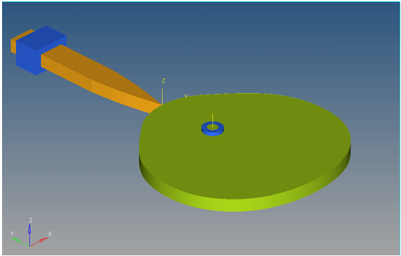
A Knife-edge Cam Follower Mechanism in MotionView
Step 6: Creating the Curve.
The curve that we will use here is the curve that defines the profile of the cam. The data for this curve has been provided in .csv format. We need to define the curve using the data in the given file.
| 1. | From the Project Browser right-click on Model and select Add Reference Entity > Curve (or right-click the Curves icon  on the Model-Reference toolbar). on the Model-Reference toolbar). |
The Add Curve dialog is displayed.
| 2. | For Label, enter CamProfile and click OK. |
| 3. | From the Properties tab, use the first drop-down menu to change the curve from 2D Cartesian to 3D Cartesian. |
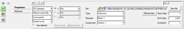
| 4. | From the Properties tab, click on the x radio button. |
| 5. | Click on the file browser icon  and select CamProfile.csv. Click Open. and select CamProfile.csv. Click Open. |
| 6. | Choose the properties of the curve as shown in the figure below: |
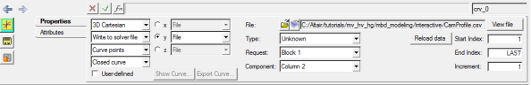
| 7. | From the Properties tab, click on the y radio button. |
| 8. | Click on the file browser icon  and select CamProfile.csv. Click Open. and select CamProfile.csv. Click Open. |
| 9. | Choose the properties of the curve as shown in the figure below: |
| 10. | From the Properties tab, click on the z radio button. |
| 11. | Click on the file browser icon and select CamProfile.csv. Click Open. |
| 12. | Choose the properties of the curve as shown in the figure below: |
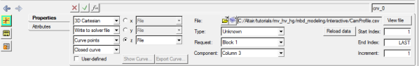
Notice the different column numbers used for x, y, and z properties.
| 13. | From the Properties tab, use the fourth drop-down menu to set the curve type to Closed Curve. |
Step 7: Creating the PTCV Joint.
Now, we will create the PTCV joint.
| 1. | From the Project Browser right-click on Model and select Add Constraint > Advanced Joint (or right-click the Advanced Joints icon  on the Model-Constraint toolbar). on the Model-Constraint toolbar). |
The Add AdvJoint dialog is displayed.
| 3. | Choose PointToCurveJoint from the drop-down menu and click OK. |
| 4. | From the Connectivity tab, double-click on Body 1. |
The Select a Body dialog gets displayed. Choose Follower and click OK.
| 5. | From the Connectivity tab, double-click on Point. |
The Select a Point dialog gets displayed. Choose FollowerPoint and click OK.
| 6. | From the Connectivity tab, double-click on Curve. |
The Select a Curve dialog gets displayed. Choose CamProfile and click OK.
| 7. | From the Connectivity tab, double-click on Ref Marker. |
The Select a Marker dialog gets displayed. Choose CamMarker and click OK.
Step 8: Specifying the Cam Motion.
After we have the topology and constraints specified, we need to provide the cam motion. The most natural choice here is a uniform motion imposed on the revolute joint.
| 1. | From the Project Browser right-click on Model and select Add Constraint > Motions (or right-click the Motions icon  on the Model-Constraint toolbar). on the Model-Constraint toolbar). |
The Add Motion or MotionPair dialog is displayed.
| 2. | For Label, enter CamMotion and click OK. |
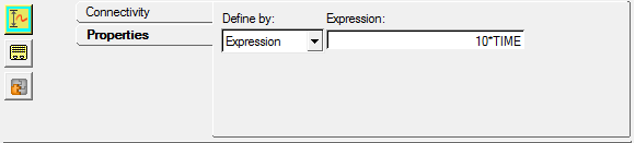
| 3. | From the Connectivity tab, double-click on Joint. Choose CamPivot and click OK. |
| 4. | From the Properties tab, specify the properties as `10*TIME`. |
Step 9: Specifying Gravity.
Since our shaft is along the Y-axis, we want the gravity to be in the negative Y direction. To specify this:
| 1. | Click the Forms icon  on the Model-General toolbar. on the Model-General toolbar. |
The Forms panel is displayed.
| 2. | Select Gravity and specify the following values: |
Direction
|
Value
|
X
|
0
|
Y
|
-9810
|
Z
|
0
|
Step 10: Specifying Output Requests.
We would like to monitor the reaction on PTCV joint since it can help us verify the correctness of our results. This will be discussed in detail towards the end of the tutorial when the topic of 'lift-offs' will be discussed.
| 1. | From the Project Browser right-click on Model and select Add General MDL Entity > Output (or right-click the Outputs icon  on the Model-General toolbar). on the Model-General toolbar). |
The Add Output dialog is displayed.
| 2. | For Label, enter PTCV Reaction and click OK. |
| 3. | From the Properties tab, choose Expressions from the drop-down menu. |
| 4. | Click in the F2 expression box. |
| 5. | Click on the  button. button. |
The Expression Builder dialog is displayed.
| 6. | Populate the expression as 'PTCV({aj_0.idstring},0,2,0)'. |
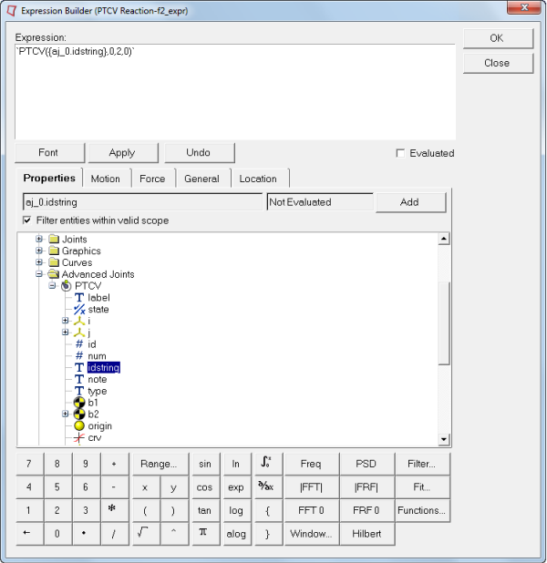
| 8. | Repeat the process for F3, F4, F6, F7, and F8 by changing the 3rd parameter to 3, 4, 6, 7, and 8 accordingly. |
The PTCV(id, jflag, comp, ref_marker) function returns the reaction on the PTCV joint:
id
|
ID of the PTCV joint
|
jflag
|
0 gives reaction on the I-marker and 1 on J-marker
|
comp
|
component of the reaction
|
ref_marker
|
reference marker (0 implies Global Frame)
|
Step 11: Running the Model.
We now have the model defined completely and it is ready to run.
| 1. | Click the Run icon  on the toolbar. on the toolbar. |
The Run panel is displayed.
| 2. | From the Main tab, specify values as shown below: |
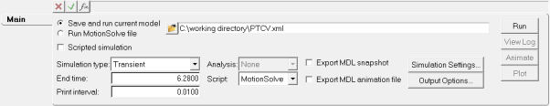
| 3. | Choose the Save and run current model radio button. |
| 4. | Click on the browser icon and specify a file name of your choice. |
| 6. | Click Check Model button  on the Model Check toolbar to check the model for errors. on the Model Check toolbar to check the model for errors. |
| 7. | To run the model, click the Run button on the panel. |
The solver will get invoked here.
Step 12: Viewing the Results.
| 1. | Once the solver has finished its job, the Animate button will be active. Click on Animate. |
The  icon can be used to start the animation, and the
  icon can be used to stop/pause the animation.
One would also like to inspect the displacement profile of the follower in this mechanism. For this, we will plot the Y position of the center of mass of the follower.
| 2. | Use the Page Layout drop-down menu  on the Page Controls toolbar to select the three-window layout on the Page Controls toolbar to select the three-window layout  . . |
| 3. | Highlight the lower right window and use the Select application drop-down menu to change the application from MotionView  to HyperGraph 2D to HyperGraph 2D  . . |
| 4. | Click the Build Plots  icon on the Curves toolbar. icon on the Curves toolbar. |
| 5. | Click on the browser icon  and load the result.abf file. and load the result.abf file. |
| 6. | Make selections for the plot as shown below: |
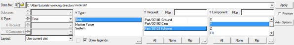
We are plotting the Y profile of the center of mass of the follower.
| 8. | The profile for the Y-displacement of the follower should look like the one shown below: |
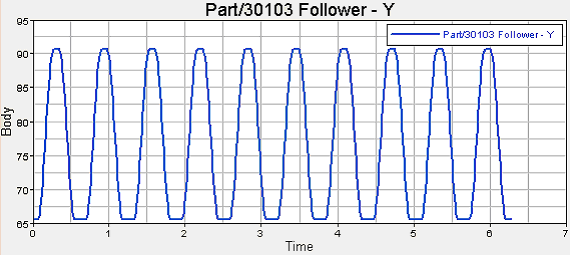
| 9. | If we set the X-axis properties to zoom in on one cycle, the profile looks as shown below: |
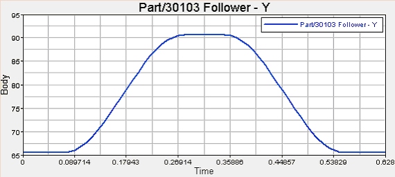
The profile of the cam has been designed to obtain the above Y-profile for the follower.
Now, we come to the discussion regarding ‘lift-offs’. In some cases, the dynamics of the system may cause the follower to lose contact with the cam. This is called ‘lift-off’. In such cases, modeling the system using a PTCV joint will give us incorrect results. This is because the PTCV joint constrains the follower point to be always on the curve and hence cannot model lift-offs. For such cases, contact modeling has to be used (refer tutorial MV-1010 for contact modeling). However, one would like to start with a PTCV model since modeling a PTCV joint is a lot easier than modeling contact. Given this scenario, the following modeling steps should be followed:
| 1. | Model the system using a PTCV joint. |
| 2. | Monitor the PTCV joint reaction. If the reaction on the follower is a ‘pulling’ reaction, it means lift-off would have occurred and one needs to go for a contact model. Otherwise, the PTCV model is good enough. |
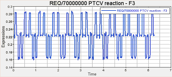
Now, let’s check if our PTCV model is good enough. For this, we need to plot the reaction profile on the follower. Since the follower is moving along the Y-axis, any negative reaction along the Y-axis is a ‘pulling’ reaction. So, let’s plot the Y-reaction on the follower. For this:
| 3. | Add a new page to the session by clicking on the Add Page icon  . . |
| 4. | Choose HyperGraph 2D and click on Build Plots . |
| 5. | Click on the browser icon  and load the result.abf file. and load the result.abf file. |
| 6. | Make selections for the plot as shown below: |
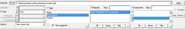
We are plotting the Y profile of the PTCV reaction on the follower.
The profile should look like the one shown below:
If we zoom in on one cycle by scaling the X-axis, the profile looks like this:
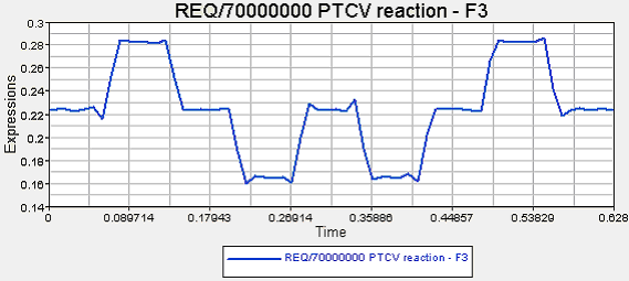
We see that the Y component of the PTCV reaction on the follower is always positive and hence it is never a ‘pulling’ reaction. Thus, our PTCV model is good enough to model the dynamics since there is no expected lift-off.
In this tutorial, we learned how to model a PTCV joint and use it to model a cam-follower mechanism. We also discussed lift-offs and ways of verifying the suitability of a PTCV joint model for modeling the dynamics of a particular system.


