MV-8001: Path and Velocity Following |

|

|

|

|
|
MV-8001: Path and Velocity Following |

|

|

|

|
In this tutorial, you will learn how to:
| • | Define a path and velocity or acceleration profile |
| • | Set up a feedforward steering controller to follow a path |
| • | Set up a feedforward traction controller to follow a velocity or acceleration profile |
| • | In a feed-forward system, the control variable adjustment is not error-based. Instead it is based on knowledge about the process in the form of a mathematical model of the process and knowledge about or measurements of the process disturbances. |
| • | In simpler words, controller that uses the knowledge about the vehicle, to compute the signals |
| • | Assume, a driver who knows that the vehicle weighs 1000 Kg and 30% throttle produces 1000 N of force in forward direction. If asked to produce 1 m/s2 of acceleration would simply give 30% throttle. |
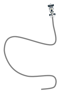
Multiple methods can be used to provide the desired path:
| • | Table of centerline points: Path is provided as a table of equally spaced cartesian coordinates of centerline points. These points are provided in a separate file, DDF or Driver Demand File. |
$Example DDF
[ALTAIR_HEADER]
FILE_TYPE = 'DDF'
FILE_VERSION = 1.0
FILE_FORMAT = 'ASCII'
$---------------------------------------------------UNITS
[UNITS]
(BASE)
{length force angle mass time}
'm' 'newton' 'degrees' 'kg' 'sec'
$---------------------------------DEMAND_VECTORS
[DEMAND_VECTORS]
{X Y Z}
0 0 0
-4 0 0
-1 0 0
-2 0 0
-5 0 0
-3 0 0

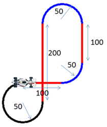
| • | Sequence of straights and arcs: Path is provided as a table of straights and circular section. |
KEY |
PAR0 |
PAR1 |
||||
|---|---|---|---|---|---|---|
ST |
Length of the straight section |
Unused |
||||
ARC |
Radius of curvature |
Angle of the arc
|
[PATH]
{KEY PAR0 PAR1}
'ST' 100.0 0
'ARC' 50.0 1.57079
'ST' 100.0 0
'ARC' 50.0 3.14159
'ST' 200.0 0
'ARC' 50.0 -2.35619

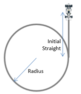
| • | Predefined path: Path is one of the predefined paths visualization (Constant Radius, Single lane change, Double lane change, and Slalom). |
$Example block for constant radius path
[PATH]
TYPE = 'CONSTANT_RADIUS'
RADIUS = 30
INITIAL_STRAIGHT = 45
TURN = 'LEFT‘

| • | Demand velocity or acceleration profile is similar to open loop signal explained in tutorial 1. All methods – constant, expression and curve are valid for demand signal definition as well. |
Exercise
Step 1: Assembling the vehicle.
| 1. | Follow the instructions in Step #1 of MV-8000 to create the vehicle with the topology as provided below. |
Page |
Label |
Selection |
Default (Yes/No) |
|---|---|---|---|
1 |
Model type |
Full vehicle with advanced driver |
No |
2 |
Driveline configuration |
Front wheel drive |
Yes |
3 |
Vehicle body |
Body |
Yes |
3 |
Front suspension |
Frnt macpherson susp (1 pc. LCA) |
Yes |
3 |
Steering linkages |
Rackpin steering |
Yes |
3 |
Rear subframe |
None |
Yes |
3 |
Rear suspension |
Rear quadlink susp |
Yes |
3 |
Powertrain |
Linear torque map powertrain |
Yes |
3 |
Signal generator |
Driver signal generator |
Yes |
3 |
Tires |
FIALA/HTIRE |
Yes |
4 |
Steering column |
Steering column 1 (not for abaqus) |
Yes |
4 |
Steering boost |
None |
Yes |
5 |
Front struts |
Frnt strut (with inline jts) |
Yes |
5 |
Front stabilizer bars |
None |
Yes |
5 |
Rear struts |
Rear strut (with inline jts) |
Yes |
5 |
Rear stabilizer bars |
None |
Yes |
6 |
Front jounce bumpers |
None |
Yes |
6 |
Front rebound bumpers |
None |
Yes |
6 |
Rear jounce bumpers |
None |
Yes |
6 |
Rear rebound bumpers |
None |
Yes |
7 |
Disk brakes |
Disk brakes |
Yes |
7 |
Front driveline |
Independent fwd |
Yes |
8 |
|
Next |
No |
9 |
|
Finish |
No |
Step 2: Adding driver analysis.
| 1. | Use the Task Wizard to load the driver analysis. |

Step 3: Specifying vehicle parameters
| 1. | We are going to use feedforward controllers for path and velocity profile following. Feedforward controllers model the vehicle and therefore, require vehicle parameters. Vehicle parameters need not be precise for controllers to work. Most of the vehicle parameters required by the driver can be automatically calculated from the vehicle model. |
Step 4: Writing an Altair Driver File (ADF) driving event .
| 1. | Open any text editor and copy and paste the following text into it. Be sure to read through the comments for a better understanding on what is written in the ADF. |
$-----------------------------------------------------------------ALTAIR_HEADER
$ This block is required for version control
[ALTAIR_HEADER]
FILE_TYPE = 'ADF'
FILE_VERSION = 1.0
FILE_FORMAT = 'ASCII'
$--------------------------------------------------------------------------UNITS
$In this block we specify the units in which this file should be read
[UNITS]
(BASE)
{length force angle mass time}
'meter' 'newton' 'radians' 'kg' 'sec'
$--------------------------------------------------------------------VEHICLE_IC
$In this block we specify the initial conditions specifically initial speed of the
$vehicle with respect to the vehicle IC marker in the driver attachments
[VEHICLE_INITIAL_CONDITIONS]
VX0 = -15.0
VY0 = 0.0
VZ0 = 0.0
$--------------------------------------------------------------STEERING_STANDARD
$This block specifies the saturation and cutoff frequency for the low pass filter for
$steering output signal. These signals are global and are active for the entire event
[STEER_STANDARD]
MAX_VALUE = 3.141593
MIN_VALUE = -3.141593
SMOOTHING_FREQUENCY = 10.0
INITIAL_VALUE = 0.0
$--------------------------------------------------------------THROTTLE_STANDARD
$This block specifies the saturation and cutoff frequency for the low pass filter for
$throttle output signal
[THROTTLE_STANDARD]
MAX_VALUE = 1.0
MIN_VALUE = 0.00
SMOOTHING_FREQUENCY = 10.0
INITIAL_VALUE = 0.5
$---------------------------------------------------------------BRAKING_STANDARD
$This block specifies the saturation and cutoff frequency for the low pass filter for
$brake output signal
[BRAKE_STANDARD]
MAX_VALUE = 1.0
MIN_VALUE = 0.0
SMOOTHING_FREQUENCY = 10.0
INITIAL_VALUE = 0.0
$-----------------------------------------------------------------MANEUVERS_LIST
$This block provides the list of all the maneuvers, simulation time for each maneuver
$maximum solver step size (hmax) and print interval
[MANEUVERS_LIST]
{ name simulation_time h_max print_interval}
'MANEUVER_1' 15.0 0.005 0.01
$---------------------------------------------------------------------MANEUVER_1
[MANEUVER_1]
$This block provides the ties controllers to each driver output
TASK = 'STANDARD'
(CONTROLLERS)
{DRIVER_SIGNAL PRIMARY_CONTROLLER ADDITIONAL_CONTROLLER}
STEER FEEDFORWARD_STEER NONE
THROTTLE FEEDFORWARD_TRACTION NONE
BRAKE FEEDFORWARD_TRACTION NONE
$---------------------------------------------------------STEER
$This is controller block containing all the information required by
$the driver to construct the controller. Different controllers have
$different requirements. Here we are using feedforward steering
$controller.
[FEEDFORWARD_STEER]
TAG = 'FEEDFORWARD'
LOOK_AHEAD_TIME = 0.5
PATH = 'PREDEFINED'
BLOCK = 'PATH'
$---------------------------------------------------------PATH
$Block containing the information about the path to be followed
[PATH]
TYPE = 'CONSTANT_RADIUS'
RADIUS = 40
INITIAL_STRAIGHT = 20
TURN = 'LEFT'
$--------------------------------------------------THROTTLE & BRAKE
[FEEDFORWARD_TRACTION]
TAG = 'FEEDFORWARD'
TYPE = 'FOLLOW_VELOCITY'
LOOK_AHEAD_TIME = 0.5
DEMAND_SIGNAL = 'DEMAND_SPEED'
$---------------------------------------------------------DEMAND_SPEED
$Block containing all the information about the velocity profile to be followed
[DEMAND_SPEED]
TYPE = 'CONSTANT'
VALUE = 15.0
| 2. | Save the ADF. |
| 3. | Run the simulation |
| 4. | Observe the results. |
| 5. | Next let's try the same path using another method - Sequence of straight and arcs. |
| 6. | Change the PATH attribute in the FEEDFORWARD_STEER block in the ADF to SEQUENCE_OF_ST_CRV. |
[FEEDFORWARD_STEER]
TAG = 'FEEDFORWARD'
LOOK_AHEAD_TIME = 0.5
PATH = 'PREDEFINED SEQUENCE_OF_ST_CRV '
BLOCK = 'PATH'
| 7. | Replace the path block in the ADF with the following text. |
[PATH]
{KEY PAR0 PAR1}
'ST' 20 0
'ARC' 40 6.28318
| 8. | Rerun the simulation. This is simply a change in the method of providing the same path and therefore, should make any difference in the results. |
In this example we will create an event to follow a straight line while accelerating the vehicle constantly with 2 m/s2.
| 1. | Open any text editor and copy/paste the following text into it. |
$-----------------------------------------------------------------ALTAIR_HEADER
[ALTAIR_HEADER]
FILE_TYPE = 'ADF'
FILE_VERSION = 1.0
FILE_FORMAT = 'ASCII'
$--------------------------------------------------------------------------UNITS
[UNITS]
(BASE)
{length force angle mass time}
'meter' 'newton' 'radians' 'kg' 'sec'
$--------------------------------------------------------------------VEHICLE_IC
[VEHICLE_INITIAL_CONDITIONS]
VX0 = -20.0
VY0 = 0.0
VZ0 = 0.0
$--------------------------------------------------------------STEERING_STANDARD
[STEER_STANDARD]
MAX_VALUE = 3.141593
MIN_VALUE = -3.141593
SMOOTHING_FREQUENCY = 10.0
INITIAL_VALUE = 0.0
$--------------------------------------------------------------THROTTLE_STANDARD
[THROTTLE_STANDARD]
MAX_VALUE = 1.0
MIN_VALUE = 0.00
SMOOTHING_FREQUENCY = 10.0
INITIAL_VALUE = 0.2
$---------------------------------------------------------------BRAKING_STANDARD
[BRAKE_STANDARD]
MAX_VALUE = 1.0
MIN_VALUE = 0.0
SMOOTHING_FREQUENCY = 10.0
INITIAL_VALUE = 0.0
$-----------------------------------------------------------------MANEUVERS_LIST
[MANEUVERS_LIST]
{ name simulation_time h_max print_interval}
'MANEUVER_1' 10.0 0.01 0.01
$---------------------------------------------------------------------MANEUVER_1
[MANEUVER_1]
$This block provides the ties controllers to each driver output
TASK = 'STANDARD'
(CONTROLLERS)
{DRIVER_SIGNAL PRIMARY_CONTROLLER ADDITIONAL_CONTROLLER}
STEER FEEDFORWARD_STEER NONE
THROTTLE FEEDFORWARD_TRACTION NONE
BRAKE FEEDFORWARD_TRACTION NONE
$---------------------------------------------------------STEER
$This is controller block containing all the information required by
$the driver to construct the controller. Different controllers have
$different requirements. Here we are using feedforward steering
$controller.
[FEEDFORWARD_STEER]
TAG = 'FEEDFORWARD'
LOOK_AHEAD_TIME = 0.5
PATH = 'PREDEFINED'
BLOCK = 'PATH'
$---------------------------------------------------------PATH
$Block containing the information about the path to be followed
[PATH]
TYPE = 'CONSTANT_RADIUS'
RADIUS = 40
INITIAL_STRAIGHT = 20
TURN = 'LEFT'
$--------------------------------------------------THROTTLE & BRAKE
[FEEDFORWARD_TRACTION]
TAG = 'FEEDFORWARD'
TYPE = 'FOLLOW_VELOCITY FOLLOW_ACCELERATION'
LOOK_AHEAD_TIME = 0.5
DEMAND_SIGNAL = 'DEMAND_SPEEDDEMAND_ACC'
$---------------------------------------------------------DEMAND_ACC
$Block containing all the information about the acceleration profile to be followed
[DEMAND_SPEED]
TYPE = 'CONSTANT'
VALUE = 2.0
| 2. | Run the simulation and study the results. |
In this example we’ll give path as a table of Cartesian coordinated of centerline points. We’ll define the velocity profile as well along the path.
| 1. | Open text editor and copy/paste the following text into it. |
$-----------------------------------------------------------------ALTAIR_HEADER
[ALTAIR_HEADER]
FILE_TYPE = 'ADF'
FILE_VERSION = 1.0
FILE_FORMAT = 'ASCII'
$--------------------------------------------------------------------------UNITS
[UNITS]
(BASE)
{length force angle mass time}
'meter' 'newton' 'radians' 'kg' 'sec'
$--------------------------------------------------------------------VEHICLE_IC
[VEHICLE_INITIAL_CONDITIONS]
VX0 = -20.0
VY0 = 0.0
VZ0 = 0.0
$--------------------------------------------------------------STEERING_STANDARD
[STEER_STANDARD]
MAX_VALUE = 3.141593
MIN_VALUE = -3.141593
SMOOTHING_FREQUENCY = 10.0
INITIAL_VALUE = 0.0
$--------------------------------------------------------------THROTTLE_STANDARD
[THROTTLE_STANDARD]
MAX_VALUE = 1.0
MIN_VALUE = 0.00
SMOOTHING_FREQUENCY = 10.0
INITIAL_VALUE = 0.2
$---------------------------------------------------------------BRAKING_STANDARD
[BRAKE_STANDARD]
MAX_VALUE = 1.0
MIN_VALUE = 0.0
SMOOTHING_FREQUENCY = 10.0
INITIAL_VALUE = 0.0
$-----------------------------------------------------------------MANEUVERS_LIST
[MANEUVERS_LIST]
{ name simulation_time h_max print_interval}
'MANEUVER_1' 10.0 0.01 0.01
$---------------------------------------------------------------------MANEUVER_1
[MANEUVER_1]
TASK = 'STANDARD'
(CONTROLLERS)
{DRIVER_SIGNAL PRIMARY_CONTROLLER ADDITIONAL_CONTROLLER}
STEER FEEDFORWARD_STEER NONE
THROTTLE FEEDFORWARD_TRACTION NONE
BRAKE FEEDFORWARD_TRACTION NONE
$---------------------------------------------------------STEER
[FEEDFORWARD_STEER]
TAG = 'FEEDFORWARD'
LOOK_AHEAD_TIME = 0.5
$Instruction to the driver that the path is of type DDF
PATH = 'DDF'
$Path of the ddf file, data lies in same folder in file named snet.ddf
FILE = 'snet.ddf'
$--------------------------------------------------THROTTLE & BRAKE
[FEEDFORWARD_TRACTION]
TAG = 'FEEDFORWARD'
TYPE = 'FOLLOW_VELOCITY'
LOOK_AHEAD_TIME = 0.5
DEMAND_SIGNAL = 'DEMAND_SPEED'
$---------------------------------------------------------DEMAND_SPEED
$Block containing all the information about the acceleration profile to be followed
[DEMAND_SPEED]
TYPE = 'CURVE'
$Velocity profile information is in the file snet.ddf in the same folder
$Velocity profile is defined under the column name DV in the DDF
${X Y Z DV}
FILE = 'snet.ddf'
DEMAND_VECTOR = 'DV'
| 2. | Place snet.adf in the same folder as the ADF. |
| 3. | Run the simulation and study the results. |
| 4. | Alternatively, edit the DEMAND_SPEED block to be a curve as a function of distance traveled along the centerline. Replace the DEMAND_SPEED block in the ADF with the following text. |
[DEMAND_SPEED]
TYPE = 'CURVE'
BLOCK = 'DEMAND_CURVE'
$-------------------------DEMAND_CURVE
[DEMAND_CURVE]
INDEPENDENT_VARIABLE = 'PATH_S'
DEPENDENT_VARIABLE = SIGNAL
INTERPOLATION = 'LINEAR'
{PATH_S SIGNAL}
0 30
250 35
400 10
584 10
680 25
780 10
942 10
1300 40
1695 10
1868 10
1958 10
2040 15
2109 15
2173 15
2300 20
2409 15
2524 15
2647 10
2811 10
3500 50