|
»Click here to display Table of Contents«
|

Rear Twist Beam |

|

|

|

|
|
Rear Twist Beam |
|
|
|

|
|
»Click here to display Table of Contents«
|
Rear Twist Beam |
|
|
|
|
|
Rear Twist Beam |
|
|
|
|
A Rear Twist Beam suspension is included in the Vehicle Library. This configuration is also known as “torsion beam axle” suspension. They are named twist axles, because the axle must twist when the vehicle rolls. The beam holds the two trailing arms together, and provides the roll stiffness of the suspension by twisting as the two trailing arms move relative to each other. This suspension is widely used on small inexpensive passenger cars.
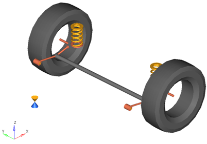
Rear Twist Beam Suspension
There are three types of twist beam suspension systems. The difference is in the location of the cross beam.
| • | The first type has the beam at the bushing center. |
| • | The second type has the beam partway between the bushings and the wheel center. |
| • | The third type has the cross beam at the wheel centers. |
The figure shown above is a rear wheel twist beam suspension system of the second type. The model can be easily modified to represent all three types of axles.
The Rear Twist Beam suspension offers a standard set of attachments, options, and properties that you can set by selecting the suspension system in the Project Browser to display the System/Assembly panel.
Attachments determine how the suspension connects to the rest of the vehicle. The Rear Twist Beam includes attachments for the trailing arm and the optional track bar:
| - | The trailing arm and track bar attach to the sub-frame by default. When a sub-frame is not present in the model, the Assembly Wizard attaches the trailing arm and track bar to the vehicle body. If the vehicle body is not present, for example in a half vehicle model, then the Assembly Wizard will attach them to ground. You can set the attachment for the trailing arm and the track bar using the Attachment Wizard from the Model menu, or by selecting the Rear Twist Beam suspension system in the Project Browser and revising the attachments within the Attachments tab on the System/Assembly panel. |
The Rear Twist Beam suspension like all Vehicle Library suspension systems includes a Compliant option. When the Rear Twist Beam suspension’s Compliant option is set to No, the trailing arm bushings are replaced with revolute joints, with the rotational axis directed along the line from the left bushing to the right bushing.
The Rear Twist Beam suspension also includes a Spindle compliance option. When you set the Spindle compliance option to Yes, the wheel body connects to the wheel hub via a universal joint and bushing. The wheel hub bushing’s Kx and Ky rates determine the amount of spindle compliance introduced. To set the Spindle compliance option, select the Rear Twist Beam suspension in the Project Browser and click the Options tab on the System/Assembly panel.
The Rear Twist Beam suspension includes a static alignment dataset and form holding toe and camber variables that determine the orientation of the wheel relative to the knuckle and body in the Global coordinate system. The toe and camber variable values control the location of the spindle align point relative to the wheel center point through parametric expressions. You can view these expressions by selecting the spindle align point and examining its X, Y, and Z locations.
To set the values for toe and camber, select either the static alignment dataset or form and alter the values of the toe and camber variables. Note that the left and right wheels’ toe and camber values must be symmetric. You cannot set the toe and camber angles independently for the two wheels.
Select options using the Assembly Wizard to include stabilizer bar, spring, shock-absorber, jounce bumper, or rebound bumper subsystems in the model. In some cases you can also select where the subsystem acts, for example whether the rebound bumper is internal to the shock absorber or external.
When you finish creating your model using the Assembly Wizard, the subsystems you have chosen show in the Project Browser as children of the Rear Twist Beam suspension. The table below shows the optional subsystems available with the Rear Twist Beam suspension:
Subsystem |
Options |
Stabilizer Bar |
None |
Stabilizer Bar with Links |
Two (2) Piece Bar with Links |
Spring |
None |
Coil Springs |
---- |
Shock Absorber |
None |
Two (2) Inline Joints |
One (1) Cylindrical Joint |
Jounce Bumper |
None |
Internal Jounce Bumper |
External Jounce Bumper |
Rebound Bumper |
None |
Internal Rebound Bumper |
External Rebound Bumper |
| • | Internal jounce and rebound bumpers act between the shock tube and the shock rod. |
| • | External jounce and rebound bumpers act between the lower lateral link and the Vehicle Body. |
| • | Suspensions created without a spring or a shock absorber subsystem will not function in a full vehicle analysis. |
| • | You can alter how optional subsystems attach to the suspension by selecting the subsystem in the Project Browser and altering the subsystem’s attachments. |
Points locate the joints and bushings that connect bodies to one another in the suspension. The image below shows the principal points for the Rear Twist Beam suspension:
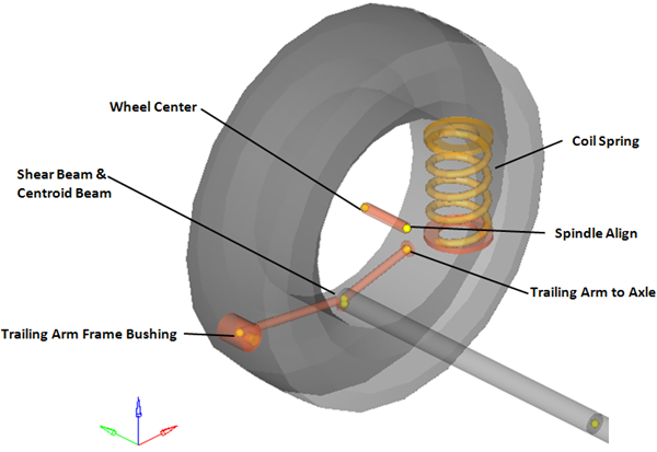
Right Side Principal Points – Rear Twist Beam Suspension
| Note | The image above omits the left side of the suspension, points locating body centers of mass, and points that locate the optional subsystems (springs, dampers, bump stops and stabilizer bar) for clarity. |
The Rear Twist Beam suspension is comprised of the bodies shown in the image below:
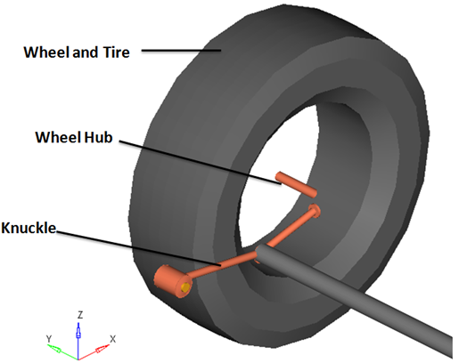
Right Side Bodies – Rear Twist Beam Suspension
| Note | The wheel hub body has no associated graphics and therefore is not visible in the image above. |
Optional subsystems may add bodies to the suspension, for example the shock absorber adds two bodies: a shock rod and shock tube. Any bodies added by optional subsystems have been omitted from the image above for clarity.
The table below describes the bodies, bushings, and joints for the Rear Twist Beam suspension:
| Note | The table omits the left side joints for clarity. |
Label |
Type |
Body 1 |
Body 2 |
Point |
Notes |
|---|---|---|---|---|---|
Wheel Spindle Joint |
Revolute |
Wheel Hub |
Knuckle |
Wheel Center |
---- |
Wheel Hub Fix Joint |
Fixed |
Wheel |
Wheel Hub |
Wheel Center |
When the Spindle compliance option is set to Yes, the joint type changes to universal. |
Trailing Arm Bush |
Revolute |
Knuckle |
Vehicle Body |
Trail Arm Frame |
---- |
The figure below shows the location of the joints and bushings in the suspension:
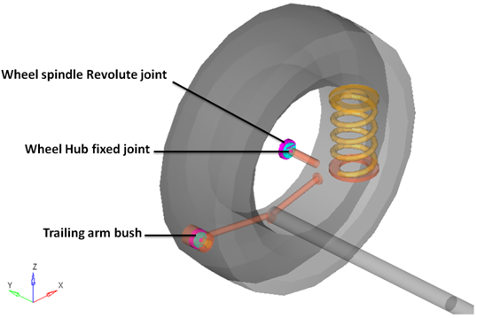
Right Side Joints and Bushings: Rear Twist Beam Suspension
The Rear Twist Beam suspension has two beams that simulate the behavior of a single beam in the suspension. Two beams are used so that the shear center can be defined differently from the area centroid. Beams shaped in a U typically require the shear center to be different from the area centroid. If a single beam is desired, delete one of the beams and enter in complete beam properties.
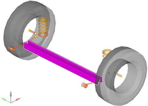
Beams used in the Rear Twist Beam Suspension
The Rear Twist Beam suspension system can be used in either a half car or a full vehicle analysis. The default geometry and mass is that of a passenger car or light truck, however the model and data can be revised to reflect any size vehicle, from a large truck to a scale model car.
| • | The wheel body represents the mass and inertia of the tire and the rim. |
| • | The wheel hub body represents the mass and inertia of other rotating bodies such as a brake rotor, but not the half-shafts if the suspension is driven. The wheel hub and brake rotor have no associated graphics. |
| • | The wheel and wheel hub parts use the Wheel CG location as the center of gravity. |
| • | Each body’s Center of Gravity (CG) is estimated from the body’s geometry. The formulas are coded into the point panel and can be seen via the graphical user interface. If more accurate CG locations are available (from a solid model or testing), they should be entered as X, Y, Z coordinates instead of the estimated number. |
| • | The model contains beams to represent the twist portion of the axle. This is a good representation of the axle early in a vehicle program. As a design is refined, the axle twist should be represented by a flexible body. |
| • | A wide variety of combinations of suspensions and subsystems can be built using the Assembly Wizard. You are encouraged to build systems and understand the resulting model using the graphical user interface. |
| • | When building a new suspension model, build the model with all of the optional systems (stabilizer bar, etc) included in the model. Immediately turn off the systems via the Project Browser and run an analysis on the base suspension to ensure it solves properly. As data becomes available for the optional systems, activate those systems and populate them with data. |
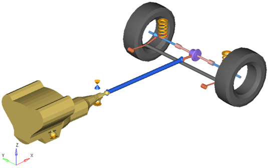
Rear-Half-Vehicle Model Employing a Twist Beam Suspension and a Powertrain
The image below shows the MotionView Project Browser view of the systems in a fully populated rear suspension model. The Rear twistbeam susp system has three “child” systems.
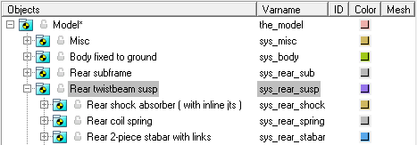
Browser view of a Rear-Half-Vehicle Model Systems and Subsystems Employing a Twist Beam Suspension