This tutorial shows you how to implement a single input single output (SISO) controller in MotionView and solve it using MotionSolve.
Consider the problem of maintaining the reference speed of a rotor in the presence of disturbances. A block diagram of the control system is shown in Figure 1 below.
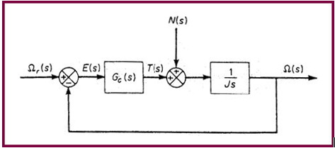
Figure 1 - Block diagram of the control system.
One simple approach is to design a proportional integral (PI) controller (Ogata, 1995), such that:
This tutorial shows you how to implement this PI controller.
Exercise
Step 1: Loading the rotor model.
| 1. | From the Start menu, select All Programs > Altair HyperWorks 14.0 > MotionView. |
| 2. | Load the rotor.mdl file, located in the motionsolve folder. |
The model contains a body called rotor that is attached to ground by a revolute joint. The joint axis is parallel to the global Z-axis. There is a torsional spring-damper with only damping and no stiffness.
The model also contains output requests for the displacement and velocity of the rotor body.
Step 2: Adding a solver variable for reference speed.
| 1. | From the Project Browser, right-click on Model and select Add General MDL Entity > Solver Variable (or right-click on the Solver Variables icon, , from the toolbar. , from the toolbar. |
The Add SolverVariable dialog will be displayed.
| 2. | Change Label to Reference Speed. |
The variable name remains sv_0.
| 5. | To maintain a linear speed of 3 rad/sec, from the Type drop-down menu, select Linear and enter 3 as the value of the solver variable. |
Step 3: Adding a SISO Controller
In this section, add a SISO controller. The input to the controller is the error between the reference speed solver variable and the rotor angular speed. The output of the controller is the torque to be applied to the rotor. The parameters for the simulation are chosen, somewhat arbitrarily, as Kp=1 and K=10.
| 1. | From the Project Browser, right-click on Model and select Add General MDL Entity > Control SISO (or right-click on the Control SISO icon,  , from the toolbar). , from the toolbar). |
The Add Control dialog will be displayed.
| 3. | From the Input tab, select Expression from the Type drop-down menu and enter this expression: |
'-WZ({MODEL.b_0.cm.idstring})+{sv_0.value}'
Note the single back quotes, indicating the expression is not to be processed by MDL, but by Templex. The parameters inside the curly braces are evaluated.
| 4. | Click the Properties tab. |
| 5. | To add Numerator coefficients, click Append. |
| 6. | Enter 10 and 1 for the coefficients of 1 and s, respectively. |
| 7. | Similarly, for Denominator coefficients, click Append and enter 0 and 1 for the coefficients of 1 and s, respectively. |
Step 4: Adding the Control Torque
In this section, create a control torque acting on the rotor body. The Z-component of this torque is the output of the controller.
| 1. | From the Project Browser, right-click on Model and select Add Force Entity > Force (or right-click on the Forces icon,  , from the toolbar). , from the toolbar). |
| 2. | The Add Force or ForcePair dialog is displayed. |
| 3. | Leave the label and variable name default settings and click OK. |
| 4. | From the Connectivity tab, under Force, select Action Reaction and for Properties, select Rotational. |
| 5. | Set Local ref. frame by double-clicking Ref Marker and selecting Global Frame. |
| 6. | Double-click Body 1 for Action force on: and select the rotor body. |
| 7. | Double-click Body 2 for Reaction force on: and select Ground Body. |
| 8. | Double-click Point 1 for Apply force at: and select Point 0. |
| 9. | Click the Rot Properties tab and leave Tx and Ty set to 0. |
| 10. | Under Tz, select Expression and enter `{MODEL.siso_0.OUTPUT}`. |
| 11. | You may also click  to access the expression builder and create this expression using the model tree. to access the expression builder and create this expression using the model tree. |
Step 5: Adding Output Requests for Control Force
| 1. | From the Project Browser, right-click on Model and select Add General MDL Entity > Output (or right-click on the Outputs icon,  , from the toolbar). , from the toolbar). |
| 2. | The Add Output dialog will be displayed. |
| 3. | Enter Control force for the Label name and click OK. |
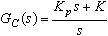
| 4. | Specify other choices as shown in figure 2 below: |
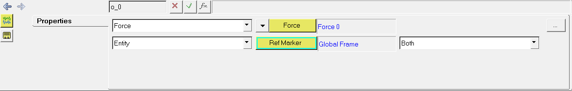
Figure 2 - Setting up the output request for control force.
Step 6: Running the Simulation
| 1. | Click the Run button,  , on the toolbar to display the Run panel. , on the toolbar to display the Run panel. |
| 2. | Under Simulation type, select Transient and specify the output (.xml) filename. |
| 3. | Enter 25 for the End time:. |
The results are displayed in the image below.
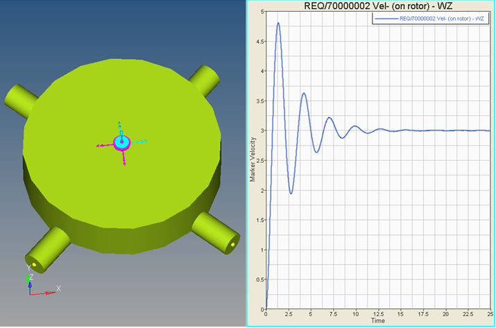
Figure 3 - Simulation results for the PI speed controller.
Reference
K. Ogata, Modern Control Engineering, 1990, Prentice-Hall Inc., Englewood Cliffs, N.J., US


