|
»Click here to display Table of Contents«
|

Single Lane Change |

|

|

|

|
|
Single Lane Change |
|
|

|

|
|
»Click here to display Table of Contents«
|
Single Lane Change |
|
|
|
|
|
Single Lane Change |
|
|
|
|
A Single lane change event drives the vehicle through a single lane change, attempting to follow the centerline of the defined lane. You can define the speed of the lane change, along with the lane dimensions. A steering controller is used to follow the path and a torque controller is used to maintain speed through the event. The event supports right and left lane changes. A plot template is available to plot the results.
A Single lane change does not have specific metrics associated with it. A lane change is typically used as a subjective evaluation test, but it is difficult to create objective metrics of the test.
Note - A Double Lane Change test is also available.
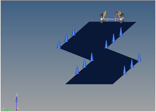
Single Lane Change Event

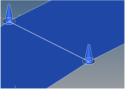
Top View of a Single Lane Change Path
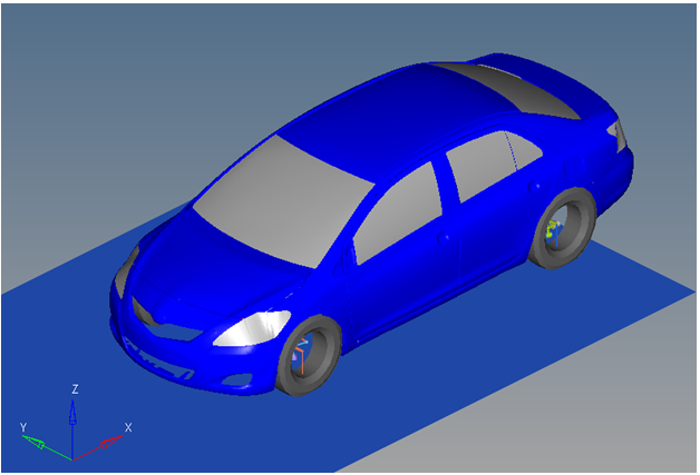
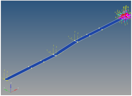
Vehicle Model with Body Graphics
The Single lane change event is designed to work with a full vehicle model that has been built through the MotionView Assembly Wizard. The event should attach to the model automatically when added through the Task Wizard. The event can be used with models built manually, as long as the attachment scheme in the event is strictly followed.
The event is comprised of an initial straight section of road, a transition section, and a recovery straight section. In the initial straight section, the vehicle settles into a steady state condition. The transition section is the actual lane change. The vehicle recovers in the final straight section and terminates the simulation. The vehicle maintains a constant velocity (via the torque controller) in the event. The vehicle steering controller is designed to keep the CG of the body on a path at the centerline of the road.
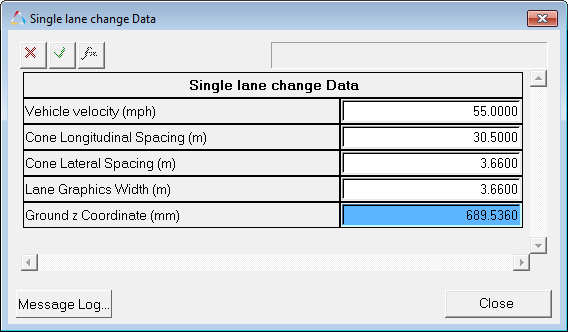
The initial speed, longitudinal and lateral spacing of the cones, and lane graphics can be modified via the event Form (shown below). The Ground z Coordinate is a calculated value (the blue background designates a calculated value) and is calculated by subtracting the front left tire rolling radius from the front left tire CG Z location.
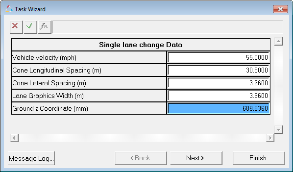
Single Lane Change Data Dialog
A test model runs this simulation in 60 seconds. Approximately 0.5G lateral is developed by the test vehicle model and default lane change parameters. Increasing the speed and lateral spacing of the cones increases the lateral G forces developed by the vehicle. As the vehicle approaches its limits of handling, the model will yaw excessively or will not complete the lane change. The error Could not Find Ideal SWA in 20 Iterations may be displayed in the log file, indicating that the steering controller is unable to follow the defined path.
The Single lane change event is parametrically defined per the diagram below.
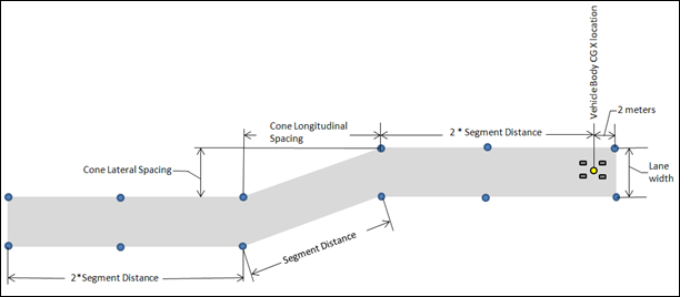
Single Lane Change Event - Road Graphics Parametric Definition
The cone spacing (laterally and longitudinally) and the lane width can be changed, along with the vehicle speed. Use the event Form to change these parameters.
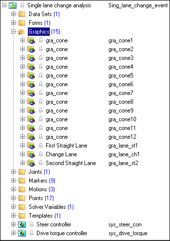
The entities in the event are displayed in the MotionView Project Browser as shown in the image below:
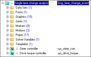
Project Browser View - Forms - Single Lane Change Analysis
Nine types of modeling element containers (Datasets->templates) are used to define the event (see below). Two sub-systems (a Steer controller and a Drive torque controller) are also included in the event.
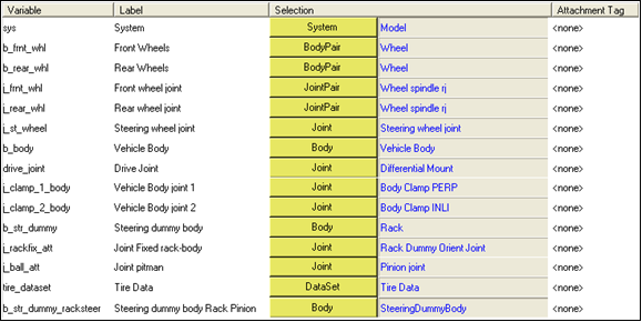
The event attaches to the model as shown in the picture below. All of the attachments need to be resolved to write out the model. The attachments are the references in the model required for the event to run.
Single Lane Change Event - Attachments
|
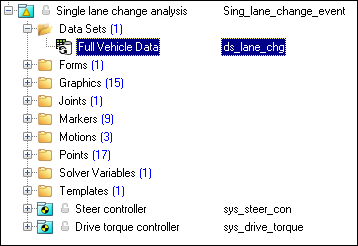
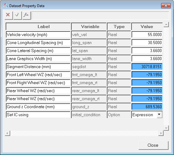
The dataset contains the data used to describe the lane change. The four parameters at the top of the dataset, shown with a white background, can be changed to modify the event using single lane change Form. The six parameters at the bottom of the dataset are calculated parameters and should not be changed. The blue background signifies a calculated parameter. The dataset should not require any user input.
Project Browser View - Datasets - Single Lane Change Analysis
Datasets Property Data Dialog - Single Lane Change Analysis |
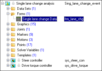
The Form is the only place that you should change the lane change event. Vehicle velocity and the lane change geometry are the parameters that can be changed. All lane change data and vehicle path graphics are defined parametrically using these four inputs (shown with a white background). The Ground z Coordinate is a calculated value (designated by a blue background) and is calculated using the left front wheel CG Z location and the tire rolling radius from the Tire Data Form.
Project Browser View - Forms - Single Lane Change Analysis
Single Lane Change Data Analysis - Form Dialog |
The road graphics are included to illustrate the path being driven and are defined parametrically using the data in the single lane change Form. All road graphics are used to illustrate the lane dimensions, but they are not of the actual road used for calculating tire forces. Road graphics should never require editing unless the event is being fundamentally changed. The road used to calculate the tire forces is at the same height as the road graphics and is defined by the road file (.rdf) in the tire system. The default flat road file in the vehicle library is an infinitely large flat road with a coefficient of friction of 1.0. The road file is an ASCII file that can be edited.
Project Browser View - Graphics - Single Lane Change Analysis
Cone Graphics
Road Graphics |
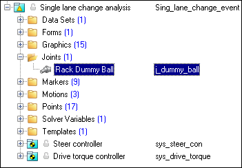
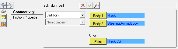
A ball joint is included in the Single lane change event. The joint attaches a dummy body to the steering rack. The joint is included to make certain events work in ADAMS. Attach the dummy body to the steering rack if building a model manually.
Project Browser View - Joints - Single Lane Change Analysis
Joints Panel - Single Lane Change Analysis |
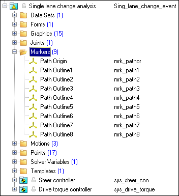
Nine markers are included in the Single lane change event. The markers are used to define the lane graphics (cones and the lane road surface). The path outline markers point to the Path Outline points for their XYZ location. The points are parametrically defined using the event input data. Path Origin is the origin of all lane change graphics and is parametrically defined to be the CG of the vehicle body. None of the markers should require any user input.
Project Browser View - Markers - Single Lane Change Analysis |
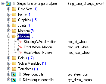
Three motions are included in the event. The motion names and a description are shown in the table below.
The steering motion is used by the steering controller to steer the vehicle and acts on a revolute joint that connects the steering column to the vehicle body. If a steering column is not included, the joint acts between the steering rack input shaft and the vehicle body. The Front and Rear Wheel Motions act on the wheel spindle revolute joints that connect the wheel hub to the knuckle. The motion is initially zero (fixing the wheels to the knuckle) so the model converges statically. The motions are deactivated after static convergence to allow the tires to rotate.
Project Browser View - Motions - Single Lane Change Analysis |
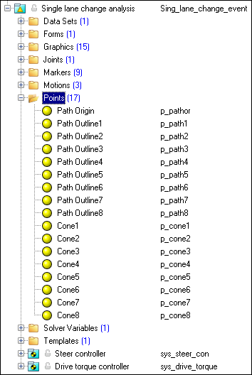
Seventeen points are defined in the event. All points are used to create the lane graphics and cones graphics used to illustrate the lanes. The points contain parametric logic to define their X, Y, and Z locations. You should not need to modify any points.
Project Browser View - Points - Single Lane Change Analysis
|
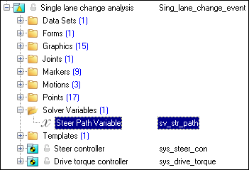
There is one solver variable in the Single lane change event. The Steer Path Variable is a user-written subroutine call which returns the steering wheel angle that should be applied to follow the desired path. The motion of the steering wheel is set to this variable in the lane change template. You should not need to edit any portion of the Steer Path Variable.
Project Browser View - Solver Variables - Single Lane Change Analysis
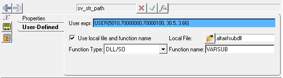
Solver Variable Panel - Steer Path Variable The numbers in the solver variable USER subroutine call are as follows:
Additional information on the steering controller is contained in the steering controller documentation section. |
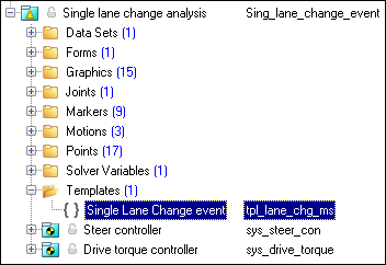
A template is included in the Single lane change event task. The template is solver specific and only the MotionSolve template is documented. The template is inserted in the solver deck after the </Model> command and controls the execution of the event. The first four commands define different output datasets. More information about these commands can be found in the MotionSolve XML Reference Guide. The if (tire_dataset.opt_omega.ival) logic is included to handle legacy models which used the omega method of tire rotation. This method is obsolete and the value will always be equal to 1. The logic will be removed in a future release. The first four deactivate commands deactivate the motion between the wheels and the knuckle, allowing them to rotate. The last two deactivate commands turn off the body clamps. Body clamps hold the body rigid during static analysis. The Motion_Joint command reassigns the value of the steering wheel joint from zero to the value calculated by the steering controller, essentially turning on the steering controller. The Simulate transient command starts the transient simulation and establishes the output time step and end time of the simulation. The data can be edited to change the event. Additional XML commands can be added to enhance the solution. The commands are described in the MotionSolve Reference Guide > Command Statements.
Project Browser View - Templates - Single Lane Change Analysis The template for this event is shown below:
|
ISO 3888-2-2011 Passenger cars — Test track for a severe lane-change maneuver.
NATO Allied Vehicle Testing Publication AVTP: 03-160 Sep. 1991.