|
»Click here to display Table of Contents«
|

Pulse Steer |

|

|

|

|
|
Pulse Steer |
|
|

|

|
|
»Click here to display Table of Contents«
|
Pulse Steer |
|
|
|
|
|
Pulse Steer |
|
|
|
|
A Pulse steer event simulates a vehicle response to a sudden pulse input to the steering wheel while driving in a straight line at a constant speed. The input to the event can be a steering wheel torque or angle, and you can set the pulse magnitude and width. The pulse can be input as a sine, step, or ramp function and you control the width. A Drive torque controller is used to maintain a constant speed, and standard outputs for the vehicle and tires are included in the Tire System and the Output Requests system. A plot template is available to plot the results.
The Pulse steer is used to characterize the dynamic response of the vehicle. The results are typically analyzed in the frequency domain to identify resonant frequencies of the vehicle. The vehicle is driven with a fixed steering wheel angle for approximately 10 seconds before and after the pulse event in order to provide sufficient data to the frequency analysis.
Pulse Steer Event
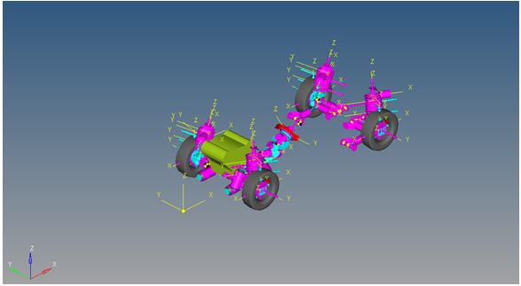
The Pulse steer event is designed to work with a full vehicle model that has been built through the MotionView Assembly Wizard. The event should attach to the model automatically when added through the Task Wizard. The event can be used with models built manually, as long as the attachment scheme in the event is strictly followed.
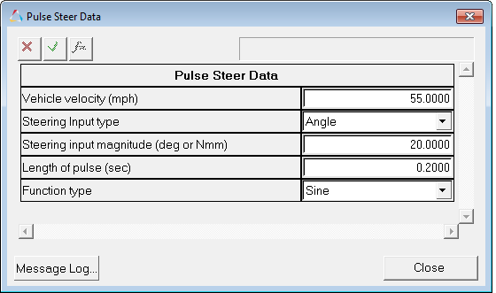
This event is used to determine vehicle response to a sudden pulsed input at the steering wheel. The event setup and sequence is described below. Event parameters are entered on the event Form shown below:
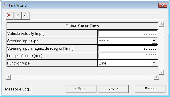
Pulse Steer Data Dialog
Input |
Units |
Description |
|---|---|---|
Vehicle Velocity |
Miles per Hour |
Velocity the vehicle maintains during the event. |
Steering Input Type |
Angle or Torque |
The type of input into the steering wheel. Angle applies a step angle into the steering wheel; torque applies a step torque into the steering wheel. |
Steering Input Magnitude |
Degrees or Newton-mm |
The magnitude of the steering input that is applied, in either degrees or Newton-mm. A positive value results in a left turn and a negative value turns the vehicle right. |
Length of Pulse |
Sec |
The length of the pulse, in seconds |
Function Type |
Sine, Step, or Ramp |
The function type used in the pulse portion of the event. |
A zoomed-in view of the steering wheel displacement pulse is shown below. The Sine wave and the step are very similar inputs. The pulse width for this input is 0.2 seconds and the magnitude is 20 degrees of the steering wheel angle. The model is typically able to drive a more accurate sine wave than a driver or a driving machine.
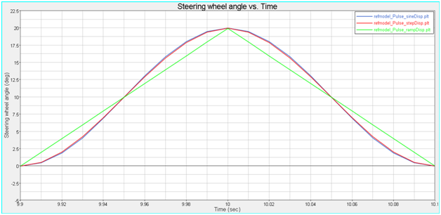
Figure – Steering Input-Sine, Step, and Ramp Pulse
The steering wheel angle for the complete event is shown below. The event runs for 20 seconds and the pulse is centered at the 10 second mark.
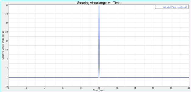
Figure - Pulse Steer Steering Input
A zoomed-in section of the steering input is shown below for a sine wave input. The Steering input magnitude and Length of pulse input parameters are shown in the graph. Modify the parameters to match your individual testing requirements.
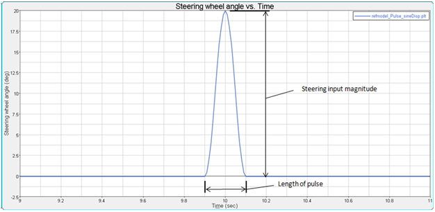
Figure - Pulse Steer Event - Pulse Description Parameters
The event sequence is described below. The Pulse steer event is a 20 second event and the pulse occurs at the center of the event. Approximately 10 seconds before and after, the pulse creates data for frequency response post-processing. Most vehicles are not symmetric, so the event can be run in both right and left steer directions by changing the sign of the Steering input magnitude.
Time |
Description |
Purpose |
|---|---|---|
0 |
Statics |
Static analysis with the vehicle fixed to ground and the wheels fixed to the hubs. |
0+ |
Joint Release |
Two joints holding the vehicle to ground and four joints holding the wheels to the spindle are released. |
0++ |
Dynamics |
Dynamic event begins with the steering wheel fixed at 0 and the torque controller maintaining constant speed. |
10-1/2 |
Pulse Begins |
The pulse event begins, using the method specified in the event Form. |
10+1/2 |
Pulse Ends |
The pulse event ends, using the method specified in the Form. |
20 |
Event End |
The event terminates. Modify the end time by editing the event template. |
| • | The steering pulse equations are defined in the event template and refer to the dataset values that are entered using the event Form. Advanced users can modify the event by editing the template. |
| • | Our studies indicate that the displacement input method is more stable than force input. |
| • | The event is run on an infinitely flat road surface with no graphics for the road. Add graphics to improve the visualization of the event. |
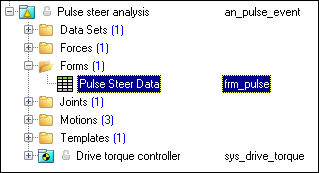
The entities in the event are displayed in the MotionView Project Browser as shown in the image below:
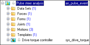
Project Browser View - Forms - Pulse Steer Analysis
Nine types of modeling element containers are used to define the event (see below). One sub-system (a Drive torque controller) is also included in the event.
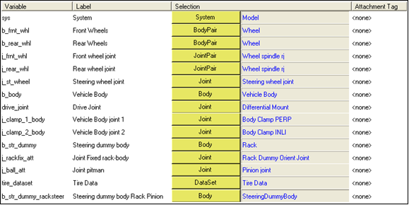
The event uses the standard event attachment. The attachments resolve automatically if the model is built through the Model Wizard. The attachments contain the minimum data the event needs to run the analysis. The attachments are standard for most events.
Pulse Steer Event - Attachments |
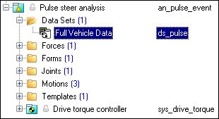
One dataset is used in the system and it contains the data used to describe the Pulse steer event. The event allows you to set the Lateral Acceleration, Circle Radius, Steer release time and Turn Direction (left or right). The initial vehicle velocity, wheel rotational velocities, and ground height are calculated values and should not be changed manually.
Project Browser View - Datasets - Pulse Steer Analysis Datasets
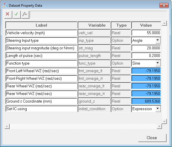
Dataset Property Dialog - Pulse Steer Analysis |
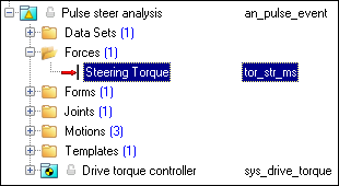
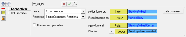
Forces are entities which apply a force or a torque to a single body or between a pair of bodies. The force in this event is used to apply a torque to the steering wheel when a force is selected as the method of application in the event Form. The browser view of the force is shown below:
Project Browser View - Force - Pulse Steer Analysis The Force panel is shown below. The force in this model is applied to the steering wheel. If the steering wheel and column are not included, the force will be applied to the steering gear input shaft.
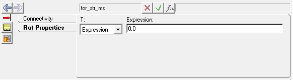
The force is initially defined as zero. The force is redefined in the event template using input from the event Form.
Force Panel |
The Form is the only place that you should change the lane change event. Lateral Acceleration, Circle Radius, Turn Direction and Steer release time are the parameters that can be changed. The Ground z Coordinate is a calculated value and is calculated using the wheel CG Z location and the tire rolling radius from the Tire Data Form.
Project Browser View - Forms - Pulse Steer Analysis
Pulse Steer Data Analysis - Form Dialog |
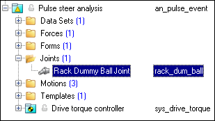
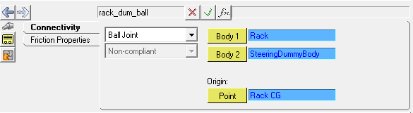
A ball joint is included in the Pulse steer event. The joint attaches a dummy body to the steering rack. The joint is included to make certain events work in ADAMS. Attach the dummy body to the steering rack if building a model manually.
Project Browser View - Joints - Pulse Steer Analysis
Joints Panel - Pulse Steer Analysis |
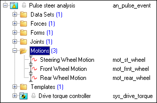
Three motions are included in the event. The steering motion to the vehicle is provided by the steering controller and acts on a revolute joint that connects the steering column to the vehicle body. If a steering column is not included in the model, the joint acts between the steering rack input shaft and the vehicle body. The Front and Rear Wheel Motions act on the wheel spindle revolute joints that connect the wheel hub to the knuckle. The motion is initially zero (fixing the wheels to the knuckle) so the model converges statically. The motions are deactivated after the static equilibrium analysis to allow the tires to rotate during the dynamic analysis.
Project Browser View - Motions - Pulse Steer Analysis |
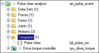
A template is included in the Pulse steer event task. The template is solver specific and only the MotionSolve template is documented. The template is inserted in the solver deck after the </Model> command and controls the execution of the event.
Project Browser View - Templates - Pulse Steer Analysis The template for this event is shown below. The template has commands for the output files that are generated, the sequence of events that are run, and the run time commands for the forces, joints and motions used to create the pulse steer event sequence.
|
ISO +7401-2003 – Road Vehicles-Lateral transient response test methods-Open-loop test methods.