Introduction
A Throttle-off cornering event simulates the dynamics of a vehicle driving a constant radius turn at steady state and the reaction of the vehicle due to a sudden removal of the drive torque while cornering. The event includes a short straight section to allow the vehicle to come to steady state, the constant radius circle, throttle removal, and the subsequent vehicle reaction. A left or right turn can be simulated. The appropriate vehicle and tire output requests are included. A plot template is available to plot the results.
Throttle-off Cornering Event
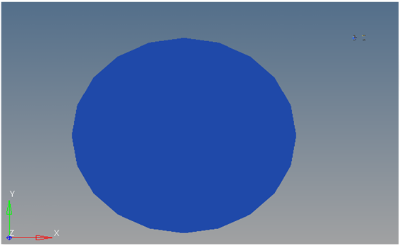
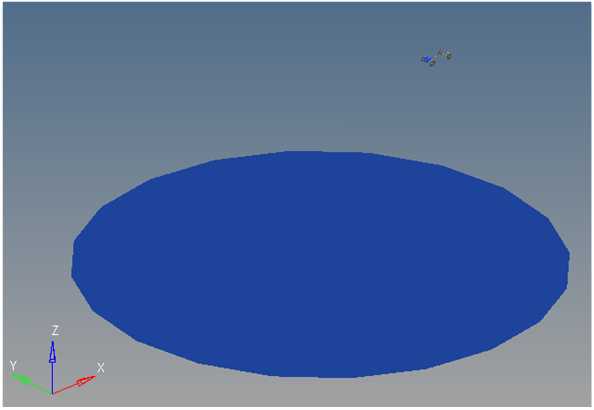
Top View of a Throttle-off Cornering Path
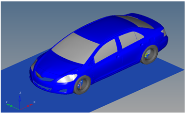
Vehicle Model with Body Graphics
Detailed Description
The Throttle-off cornering event is designed to work with a full vehicle model that has been built through the MotionView Assembly Wizard. The event should attach to the model automatically when added through the Task Wizard. The event can be used with models built manually, as long as the attachment scheme in the event is strictly followed.
In this event, the vehicle drives a short, straight section to attain steady state behavior. It then steers into the turn and is driven in the turn long enough to attain steady state cornering. The throttle torque is removed and the dynamics - due to the torque being removed - can be observed. The purpose of the test is to check the vehicle for stability during this sudden event.
It is important to note that the event does not include the effects due to engine braking. Engine braking may make the event more severe.
The event sequence is as follows:
Time
|
Description
|
0
|
Static analysis - vehicle is fixed to ground and the wheels are held so they cannot rotate.
|
0+
|
Two joints that hold the vehicle to ground are released and all four tires are allowed to rotate. Dynamic analysis begins.
|
0->turn-in
|
The vehicle drives at the prescribed speed for the entry length distance. Entry length distance is (2*π*circle radius/2) or ¼ the circumference of the circle.
|
Turn-in->
Throttle Delay Time
|
Vehicle turns into the constant radius curve and continues around the curve to reach steady state cornering.
|
Throttle Delay Time
|
Throttle is removed from the vehicle using the Throttle step duration time to go from the steady state cornering torque to zero torque.
|
Event End
|
The event ends at 20 seconds. The event end time is defined in the event template and can be modified by editing the end time value in the template that is in the final <Simulate command.
|
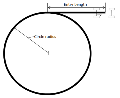
Figure - Throttle-off Cornering Path Description
The Lateral Acceleration, Circle Radius, Throttle delay and Throttle step duration can be modified via the event Form (shown below). The Turn Direction can be set to turn left or right. The Ground z Coordinate is a calculated value and should not be changed.
The speed is calculated in the event dataset (ds_thrt_cm) using the requested Lateral Acceleration, the Circle Radius, and assuming the vehicle will be in steady state cornering and following the turn radius during the event. The core equation used is Velocity=sqrt(circle radius * Lateral Acceleration). The implementation in the dataset also has the following conversion factors in the equation:
Constant
|
Template
|
1000
|
Converts meters to millimeters (1 m=1000 mm).
|
9810
|
Convert’s G’s to Acceleration (mm/sec^2) (1 G =9810 mm/sec^2).
|
447.04
|
Converts Miles/hr to mm/sec (MPH*447.04=mm/sec).
|
The entry length is fixed by the event controller and cannot be changed. The entry length distance is (2*π*circle radius/2) or ¼ the circumference of the circle. The entry length is provided so that the vehicle can reach a steady state straight line driving condition.
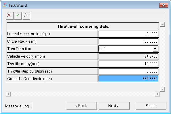
Throttle-off Cornering Data Dialog
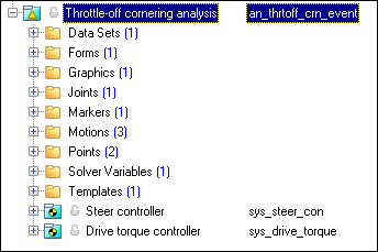
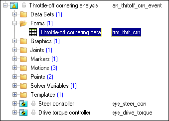
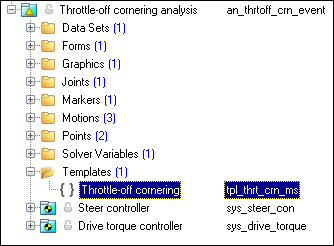
The entities of the event are displayed in the MotionView browser are shown in the image below.
Project Browser View - Forms - Throttle-off Cornering Analysis
Nine types of modeling element containers are used to define the event (see below). Three sub-systems (Output Requests, a Steer controller, and a Drive torque controller) are also included during the event.
The event uses the standard event attachment. The attachments resolve automatically if the model is built through the Model Wizard. The attachments contain the minimum data the event needs to run the analysis. The attachments are standard for most events.
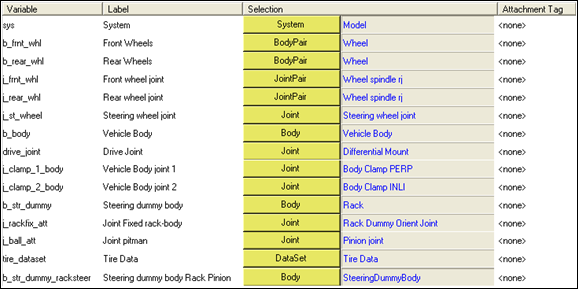
Throttle-off Cornering Event - Attachments
|
One dataset is used in the system and it contains the data used to describe the path. The event allows you to set the Lateral Acceleration, Circle Radius, Throttle delay and Throttle step duration. The Turn Direction can be set to left or right depending upon your requirements. The initial Vehicle velocity, wheel rotational velocities, and ground height are calculated values and should not be changed.
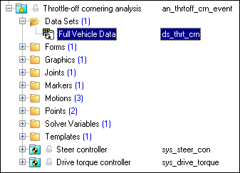
Project Browser View - Datasets - Throttle-off Cornering Analysis
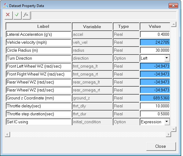
Dataset Property Data Dialog - Throttle-off Cornering Analysis
|
The Form is the only place that you should change the Throttle-off cornering event. Lateral Acceleration, Circle Radius of the path, Turn Direction, Throttle delay and Throttle step duration are the parameters that can be changed. The Ground z Coordinate is a calculated value and is calculated using the wheel CG Z location and the tire rolling radius from the Tire Data Form.
Project Browser View - Forms - Throttle-off Cornering Analysis
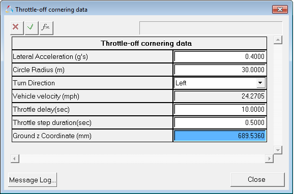
Throttle-off Cornering Data Analysis - Form Dialog
|
One graphic is defined in the event. The graphics define the road surface graphics and should not require any user input.
Skidpad graphics are included to illustrate the path being driven and are defined parametrically using the data in the Throttle-off cornering Form. Skidpad graphics should never require editing unless the event is being fundamentally changed.
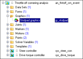
Project Browser View - Graphics - Throttle-off Cornering Analysis
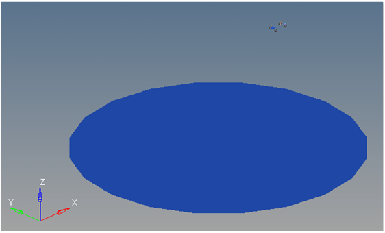
Skippad Graphics
|
A ball joint is included in the Throttle-off cornering event. The joint attaches a dummy body to the steering rack. The joint is included to make certain events work in ADAMS. Attach the dummy body to the steering rack if building a model manually.
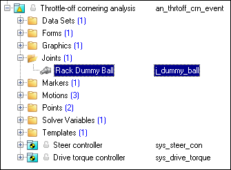
Project Browser View - Joints - Throttle-off Cornering Analysis
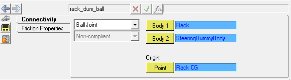
Joints Panel - Throttle-off Cornering Analysis
|
One marker is included in the Throttle-off cornering event. The path origin is the origin of skidpad graphics and is parametrically defined to be the CG of the vehicle body. The markers refer to points and the points contain the parametric logic.
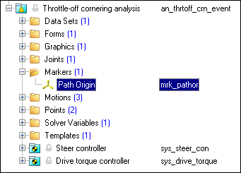
Project Browser View - Markers - Throttle-off Cornering Analysis
|
Three motions are included in the event. The steering motion is provided by the Steer controller and acts on a revolute joint that connects the steering wheel to the vehicle body. If a steering column is not included, the joint acts between the steering rack input shaft and the vehicle body.
The Front and Rear Wheel Motions act on the wheel spindle revolute joints that connect the wheel hub to the knuckle. The motion is initially zero (fixing the wheels to the knuckle) so the model converges statically. The motions are deactivated after static analysis to allow the tires to rotate during the dynamic analysis.
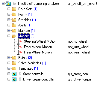
Project Browser View - Motions - Throttle-off Cornering Analysis
|
Two points are defined in the event. All points are used to create the skidpad graphics. The points contain parametric logic to define their X, Y, and Z locations. You should not need to modify any points.
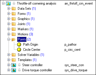
Project Browser View - Points - Throttle-off Cornering Analysis
|
The Throttle-off cornering consists of only one solver variable, the Steer Path Variable, which calls a user subroutine to apply an input at the steering wheel in order to follow the desired path.
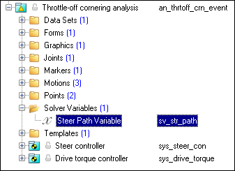
Project Browser View - Solver Variables - Throttle-off Cornering Analysis
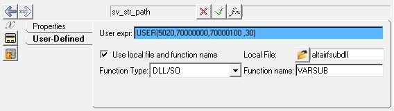
Solver Variable Panel - Steer Path Variable
The numbers in the solver variable USER subroutine call are as follows:
Number
|
Description
|
5020
|
The Branching ID. 5020 is a Throttle-off cornering event
|
70000000
|
The ID of a solver array containing Driver Model Controller data. The array is in the Steer Controller System.
|
70000100
|
The ID of a Vehicle Data Array containing vehicle information. The array is in the Steer Controller system.
|
30
|
The value of the Circle Radius.
|
|
A template is included in the Throttle-off cornering event task. The template is solver specific and only the MotionSolve template is documented. The template is inserted in the solver deck after the </Model> command and controls the execution of the event.
Project Browser View - Templates - Throttle-off Cornering Analysis
The template for this event is shown below:
<ResOutput
angle_type = "YPR"
/>
<ResOutput
mrf_file = "TRUE"
/>
<ResOutput
plt_file = "TRUE"
/>
<H3DOutput
switch_on = "TRUE"
increment = "1"
/>
<ResOutput
abf_file = "TRUE"
/>
{if (tire_dataset.opt_omega.ival ==1)}
<!--Initial static analysis -->
<Simulate
analysis_type = "Static"
end_time = "0.0"
/>
{endif}
<Deactivate
element_type = "MOTION"
element_id = "{mot_frnt_wheel.l.idstring}"
/>
<Deactivate
element_type = "MOTION"
element_id = "{mot_frnt_wheel.r.idstring}"
/>
<Deactivate
element_type = "MOTION"
element_id = "{mot_rear_wheel.l.idstring}"
/>
<Deactivate
element_type = "MOTION"
element_id = "{mot_rear_wheel.r.idstring}"
/>
{if (tire_dataset.opt_omega.ival ==2)}
<!--Initial static analysis -->
<Simulate
analysis_type = "Static"
end_time = "0.0"
/>
{endif}
<Deactivate
element_type = "JPRIM"
element_id = "{j_clamp_1_body.idstring}"
/>
<Deactivate
element_type = "JPRIM"
element_id = "{j_clamp_2_body.idstring}"
/>
<Motion_Joint
id = "{wh_motion.idstring}"
expr = "VARVAL({sv_path.idstring})"
/>
<Simulate
analysis_type = "Transient"
end_time = "20"
print_interval = "0.04"
/>
<Stop/>
|
|


