Engineering Solutions

AcuSolve Case Set Up

AcuSolve Case Set Up

Previous topic Next topic Expand/collapse all hidden text  

AcuSolve Case Set Up

Previous topic Next topic JavaScript is required for expanding text JavaScript is required for the print function  

Selecting the CFD (AcuSolve) user profile enables you to set up an AcuSolve input deck within Engineering Solutions and launch an AcuSolve run.        

hmtoggle_plus1greySolver Browser

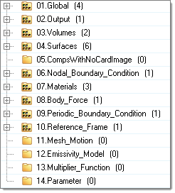
The Solver browser is used to define the set up of the input deck and contains the main folders Global, Output, Volumes, Surfaces, Components With No Card Image, Nodal Boundary Condition, Materials, Body Force, Periodic Boundary Condition, Reference Frame, Mesh Motion, Emissivity Model, Multiplier Function and Parameter.                

solver_browser_main_folders                                    

Global

Contains the physical description of the case, for example, laminar/turbulent and numerical parameters, such as convergence tolerance.  

Output

Define the frequency of different outputs: Derived Quantity Output, Nodal Output and Restart Output.

Volumes

Components with Fluid and Solid card images are grouped in this folder.

Surfaces

Components with Inflow, Outflow, Wall, Slip, Symmetry and Far Field card images are grouped in this folder.    

Components With No Card Image

Components with no card image will not be exported with the solver deck. By default, all of the components will not have a card image. You have to choose the appropriate card image for the component and the component will be moved to the Surfaces or Volumes folder accordingly.    

Nodal Boundary Condition

Define boundary conditions on nodes apart from surface boundary conditions.  

Materials

Contains material definitions.

Body Force

Define gravity and heat source for volume components.

Periodic Boundary Condition

Define periodic or axisymmetric boundaries along with the transformation definition.

Reference Frame

Define rotational reference frame for the model.

Mesh Motion

Define translation and rotation for the mesh.

Emissivity Model

Define emissivity model for radiation surface.

Multiplier Function

Define multiplier functions (Constant, Piecewise Linear, Cubic Spline, Piecewise Log Linear) and utilize multiplier functions to ramp up supported parameters, for example angular velocities of reference frame.            

Parameter

Parameters can be utilized to run solver parameter based studies.      

For example, if you want to run a series of simulations with inlet velocity values of 0.5 m/s, 0.75 m/s, 1 m/s respectively, you can define a parameter on inlet velocity with the desired values. Using the HyperStudy Job Launcher DOE studies can be performed.    

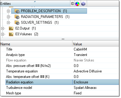
Clicking on entities in one of the main folders opens the Entity Editor, where parameters for this particular entity can be entered.            

acusolve_solver_browser2

hmtoggle_plus1greySolver Job Launcher and AcuSolve Control Tools

The Solver job Launcher enables you to execute AcuSolve jobs directly from Engineering Solutions. The tool integrates the mesh export and the AcuSolve job run. The submitted job can also be controlled from Engineering Solutions. This dialog can be invoked by clicking the clientAcuSolve-24 icon in the CFD toolbar.              

acusolve_tools_tab2

Problem name

Specifies the name of the input deck without the extension *.inp. Do not use spaces in the name.  

Problem directory

Directory where the input deck is located. The solver run will be started in the problem directory.

Working directory

The result files of the AcuSolve run will be saved into the working directory.  

Solver exec dir

Define the AcuSolve executable path. The path will be auto selected if the solver is available in the same installation path. If it is not available, the path will be blank. The path needs to point to the AcuSolve bin folder (/acusolve/win64/bin or /acusolve/linux64/bin).  

Solver module

A selection of several solver modules.

prep: Processes and prepares the input data for the solver run.

view: View factor computation for problems including radiation.

solve: Runs the solver.  

prep-solve:

all:

No. of processors

The number of processors used for this run.

Auto run AcuProbe

Automatically opens the plotting utility AcuProbe to monitor run data of the current run, for example residual.

Auto run AcuTail

Automatically opens AcuTail to view the log file of the current run.  

Output format

Converts the results of the final time step into the specified format.

Output time steps

Selecting All creates the output file in a user defined format with all of the time steps. This option is useful for a transient run.

Selecting Final creates an output file in a user defined format with only the final time step. This option should be utilized for a steady state run.    

Additional solver  arguments

Additional solver options can be specified, for example number of threads.  

Generate solver deck

If turned on, a new .inp file will be created. If turned off, an .inp file will not be generated and the program will look for the existing file.                          

Export options  

Always two layers for interfaces: Creates two interface layers between two volumes, if one or both are missing.  

Create exterior faces: Creates outer shell surface of volume if missing.        

Always add elem type to comp names: Append element configuration at the component names.  

Mapping tab

This utility allows you to extract specific output from an AcuSolve run. The extracted results will be in a .csv file. From these results you can create a field, which can be utilized to map CFD results to other structural mesh. This utility requires a finished AcuSolve run. If the mapping field is defined before the solver run, the tool will generate output in a .csv file format. This utility can be utilized any time after the solver run to extract results.        

solver_job_launcher

Variable

You can select the desired output. The options are Pressure, Velocity and Eddy viscosity. The selection list is dependent on the solver options selected (Turbulence model).    

Extract results on

You can extract results on all of the components that are selected.

Create field loads

If this checkbox is activated a field will be created automatically, which can be utilized to map the results on a structure mesh.    

Generate

This button will be activated to click if any result data is present in the working directory.        

Clicking Launch in the Solver job Launcher opens the AcuSolve Control dialog, which contains two tabs, AcuSolve and Tools.

The AcuSolve tab contains options to stop the run, restart the run, and output results.          

acusolve_control_acusolve_tab

After you click Stop, the Restart option appears. Clicking Stop stops the run as soon as the current iteration is finished. Clicking Restart restarts the job from the previous time step. When you click Output, the existing iteration result is output and you can visualize the results later on.  

The Tools tab contains options to launch or relaunch AcuProbe, AcuTail and AcuOut.

acusolve_control_tools_tab

hmtoggle_plus1greyAcuSolve Set Up Features

The following AcuSolve set up features are supported in Engineering Solutions via the Solver browser:  

Problem Description    

Title
Analysis type (Steady State or Transient)
Flow equation (Navier Stokes)
Abs. pressure offset
Temperature equation (Advective Diffusive or None)
Abs. temperature offset
Radiation equation (Enclosure or None)
Turbulence model (Laminar, Spalart Allmaras, SST, K Omega, Detached Eddy Simulation, SST DES, Dynamic LES, Classical LES)
Mesh type (Fixed or Fully Specified)  

Solver Settings

Max time steps
Final time
Initial time increment
Auto time increment
Multiplier Function
Convergence tolerance
Min stagger iterations
Max stagger iterations
Relaxation factor
Flow
Temperature
Temperature flow
Enclosure radiation
Turbulence

For full support of all AcuSolve features, please use AcuConsole. A model can be transferred from Engineering Solutions to AcuConsole by clicking the clientAcuConsole-24 icon in the CFD toolbar.