|
»Click here to display Table of Contents«
|

Assembly Tools |

|

|

|

|
|
Assembly Tools |
|
|

|

|
|
»Click here to display Table of Contents«
|
Assembly Tools |
|
|
|
|
|
Assembly Tools |
|
|
|
|
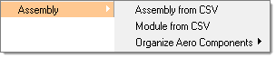
The purpose of the assembly tools is to create an assembly structure from a .csv file definition. You can create an assembly structure (product structure) similar to a PDM system using the Model/Assembly browser or using the Parts browser (Module browser). Both tools are provided using the same .csv file format described below. You can import this file and the tool automatically creates the product structure in the database. You can drag and drop components into the assembly tree to organize the models in a similar manner to CAD or PDM product structures.
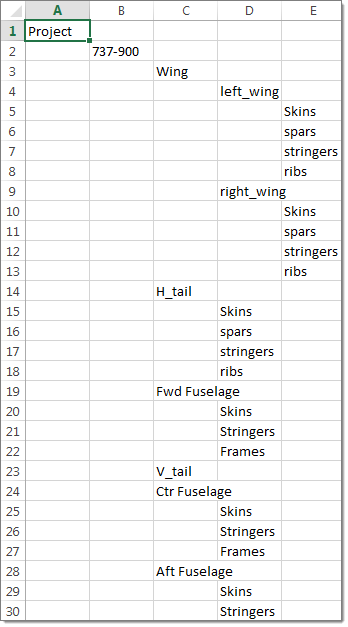
This image shows a .csv file format for the product structure definition
When you import this .csv file as an assembly or module you will get the following organization in the Model browser (assembly csv) or Part browser (module csv).
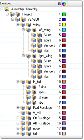
A product structure is created in the Model browser
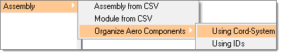
Use this tool to split a monolithic FE model (imported from solver data files) into suitable HyperWorks components. These components are then manually moved into assembly product structures to create a real world aerospace model. Two useful methods can be used to split the monolithic FE model into components. One involves using the coordinate system and the other uses ID ranges.
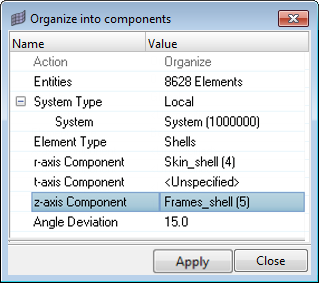
Using the coordinate systemShell and beam models can be split using a local coordinate system.
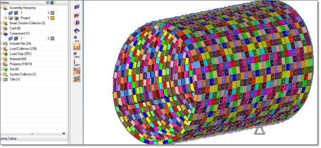
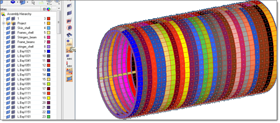
This image shows a single component model
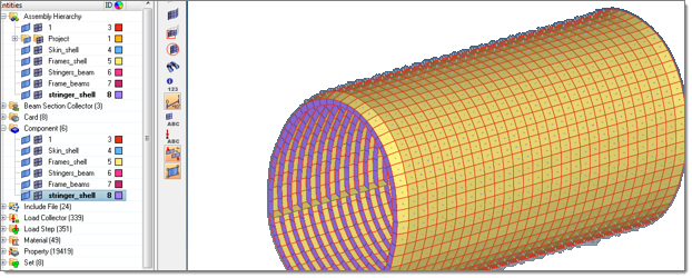
The model is split into components using the local system direction Using ID rangesAerospace users typically assign ID ranges to specific components. Using these definitions from a .csv file, the elements are automatically separated into component names defined in the .csv file.
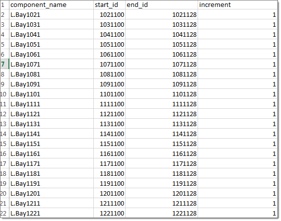
This image shows an ID range .csv file with component names
Based on ID ranges, elements are separated into components |