| Note: | In the Aerospace user profile you can open this tool via the Aerospace menu, and also via the way mentioned below. |
|
Create a midsurface mesh with a thickness from 3D geometry using the Midsurface Mesh tool.
| 1. | From the menu bar, click Mesh > Create > MidSurf Mesh to open the Midsurface Mesh tool. |
| 2. | Select solid geometry to create the mid-mesh for. |
| a. | Under Input selection, click Geometry. |
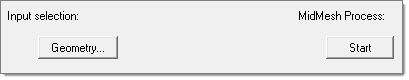
| b. | In the panel area, use the selector to select solid geometry. |
| 3. | Optional: Define pre-midsurface cleanup options. |
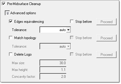
| a. | Select Pre-Midsurface Cleanup. |
| b. | Define Advanced options accordingly. |
| • | Edges equivalencing equivalences edges on the input surface. Edges can be equivalenced using an automatic or manual tolerance. This option is similar to the Edge Edit panel's equivalence subpanel. |
| • | Match topology fixes gaps between stitched edges and vertices to make the actual geometry of the surfaces consistent with the model topology. Topology can be matched using an automatic or manual tolerance. This is similar to running the *geommatchtopology command on the model. |
| • | Delete logo removes logos that appear on geometry. This is similar to the logo removal option available in the Autocleanup panel, and is based on settings from the parameter file. |
| 4. | Setup midsurface extraction. This step is mandatory unless midsurfaces have previously been generated manually. |
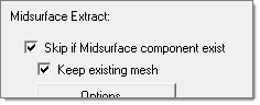
| a. | If midsurfaces were previously generated and organized into the Middle Surface component, select Skip if Midsurface component exist to skip the midsurface extraction step and preserve the current mesh. For example, if you manually extracted the Middle Surface and manually meshed some of its part (disconnected from others), then select Skip if Midsurface component exist to preserve the current Midsurface mesh and only mesh the unmeshed surfaces. If you clear this checkbox, the entire Middle Surface will be remeshed, and you will lose your current mesh. |
To preserve the mesh of the disconnected parts in the Middle Surface component that contain a mesh and only mesh the disconnected parts in the Middle Surface component that are not meshed, select Keep existing mesh. If you clear this checkbox, all of the disconnected parts in the Middle Surface component will be remeshed. This option is enabled when you select Skip if Midsurface component exist.
| b. | To define advanced auto-midsurfacing options, click Options. |
| c. | Select a method for extracting the midsurface from the Method pull-down menu. |
| • | offset + planes + sweeps uses a midsurfacing algorithm to identify the places where a piece of plane or a piece of a sweep surface can be used as a middle surface. A middle surface is constructed at the remaining places in the model, for example the places where planar or sweep surface pieces cannot be used as a middle surface, by the same algorithm as in offset via the offset of the model's sides. |
| • | offset + planes uses a midsurfacing algorithm to identify the places in the model where a piece of plane can be used as a middle surface. At the remaining places in the model, for example the places where planar pieces cannot be used as a middle surface, the same algorithm as in offset is used to construct the middle surface via the offset of the model's sides. |
| • | offset creates pieces of the middle surface by offsetting the model's side surfaces towards the middle. This is the traditional approach for midsurfacing in Engineering Solutions. |
| • | skin offset generates a midsurface by duplicating and offsetting the inner skin surfaces (those with the smallest area) and assigning them a constant thickness. The parts you provide to the algorithm must be relevant. T-connections, constant thickness, or internal ribs/features/creases are not relevant. |
| 5. | Define geometry cleanup and meshing criteria. |
| a. | Select the type of geometry cleanup and meshing to perform, and define the parameters and criteria accordingly. |
| • | Auto automatically cleans up geometry, and enables you to define an element size and a mesh type. |
| • | Custom enables you to define topology cleanup parameters and element quality criteria. The parameters and criteria options are the same as in the Autocleanup panel, and is based on settings from the parameter file. |
| b. | To sort the midsurface to the original component or to <original name~> component, select Sort Midsurfmesh component to. |
| 6. | Optional: Assign a thickness to the midsurface mesh. |
| a. | Select Thickness assignment. |
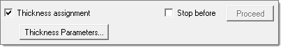
| b. | Click Thickness Parameters. |
| 7. | To pause the generation of the midsurface mesh at any step, select Step before next to the desired step to stop. By default, once you click Start, all of the above steps are executed. |
| 8. | To generate the midsurface mesh, click Start. |
| Note: | While the process is running the Proceed buttons change colors, indicating the progress of the process. |
 Blue: complete step
 Yellow: currently running step
 Green: next step to be performed (when Stop before has been activated)


