|
»Click here to display Table of Contents«
|

Auto Contact |

|

|

|

|
|
Auto Contact |
|
|
|

|
|
»Click here to display Table of Contents«
|
Auto Contact |
|
|
|
|
|
Auto Contact |
|
|
|
|
Location: Utility Browser, Tools menu > Auto Contact, and BCs menu > Create > Auto Contact. This tool is only available when the OptiStruct user profile is loaded.
The Auto Contact tool allows you to quickly and easily create one or more contact interfaces at once between several parts of your model. Based on a proximity distance, the Auto Contact tool will search throughout all of the selected components and automatically create new Contact Surfaces and contact interfaces between them. All of the contact entities found by the Auto Contact tool are displayed and organized inside a temporary Auto Contact Browser, where you can review and adjust them as needed before accepting any changes.
Auto Contact creates OptiStruct CONTACT interfaces, with different type options as available from the Type of Interface: pull-down menu in the Auto Contact dialog. The selected Type of Interface will be used as the initial configuration for all found interfaces. Afterwards, you can individually edit the type of interface in the Auto Contact Browser.
Two contact surfaces are created as Master and Slave entities per contact interface, with the following characteristics:
| • | Master and Slave surfaces are automatically assigned based on the average element size of each Contact Surface: |
| - | The Contact Surface with the smallest, average element size will be assigned as a Slave, and the other will be assigned as a Master. |
| - | The Master and Slave assignments for each contact can be reviewed and swapped in the Auto Contact Browser. |
| • | For 3D element faces, the contact surface direction will point outwards from the solid body. |
| • | For 2D elements, the contact surface direction will be assigned according to element normals, which can be reviewed and reversed in the Auto Contact Browser. |
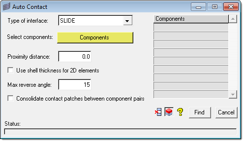
The Auto Contact dialog window contains the following options:
Option |
Description |
||||||||||||||||
Type of interface: |
Creates CONTACT interfaces using three different types of interfaces:
|
||||||||||||||||
Select components: |
Directs you to the Component Selection panel, where you can select the components to have the Auto Contact tool search through. |
||||||||||||||||
Proximity distance: |
Generates contact pairs between components that are closer to each other by less than the specified proximity distance. |
||||||||||||||||
Use shell thickness for 2D elements |
If activated, the shell thickness values will be used for 2D elements instead of the specified Proximity distance. 3D elements will still use the specified Proximity distance. |
||||||||||||||||
Max reverse angle: |
Excludes elements in the contact when the angle between the normals of two elements, or element faces within the proximity distance exceeds the specified reverse angle value. Default value is 15 deg. |
||||||||||||||||
Consolidate contact patches between component pairs |
Select this check box to consolidate any separate contact patch areas that participate in contacts between the same two components, so that the final number of contacts in the model can be reduced. When turned off (default), Engineering Solutions treats each contact patch area as a separate individual contact pair. |
||||||||||||||||
Find |
Executes the Auto Contact search between all of the components in the list. |
||||||||||||||||
Cancel |
Closes the Auto Contact dialog without applying changes. |
||||||||||||||||
Remove Selection Icon |
Removes the highlighted items from the selected components list. You can use the Ctrl and Shift keys to select multiple items in the list. |
||||||||||||||||
Review Selection Icon |
Highlights the selected items from the component table in the HyperMesh graphics area, while graying out other components. You can use the Ctrl and Shift key to select multiple items in the list. Right-click to return the model to normal display. |
||||||||||||||||
Help Icon |
Opens the Auto Contact online help. |
Remarks
During the Auto Contact process, temporary components may be created for parts containing 3D elements. These temporary components will be named using a preceding ^ symbol, and will automatically contain extracted element faces needed for the contact creation process. Auto Contact will cleanup and remove these temporary components when you finish or cancel the process. If you decide to export the model before accepting or canceling the process, HyperMesh will always exclude these temporary components from export.