Connector Entity Browser |

|

|

|

|
|
Connector Entity Browser |

|

|

|

|
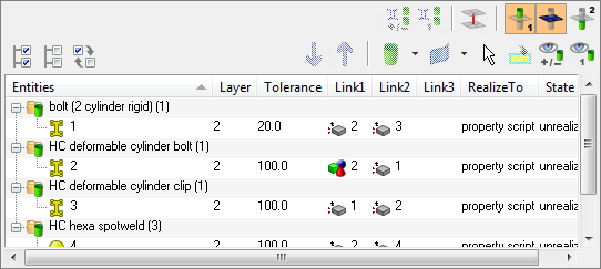
The lower section of the Connector browser contains a tree view of all the connections contained in the model, and has its own set of tools similar to the ones found in the Link Entity browser. All the connectors in the model are displayed in folders organized based on the respective realization types. The names of the folders are obtained from the FE configuration names specified for respective solvers in the feconfig.cfg file.
The connector information in the tree can be used to find link entities connected by specific connectors, and also to modify certain connector attributes. The columns display a sub-set of connector information that is important for recognizing connection information easily.
Unless all view option toggle buttons in the global display tool set are inactive, the action mode tool set and the context menu actions (show, hide, isolate, isolate only) work similarly to their functions in the Model browser's component view.
If at least one of the view option toggle buttons is active (appearing in orange), the behavior of show, hide, isolate and isolate only is different. The image on the action buttons changes to include a connector symbol, indicating the different behavior.

The actions take into account connector-link relations, and the display result depends on the active view options. Therefore parts of the model are separated into three different categories based on the connector selection:
| • | 1st connector entity: selected connectors |
| • | linked entities: links which are referenced by one of the selected connectors |
| • | 2nd connector entity: connectors which reference at least one of the linked entities |
|
This kind of categorical separation is only used for the actions show, hide, isolate and isolate only, and only when one of the view option toggle buttons is active, regardless of whether the actions are taken from the context menu or the action buttons. No other functionality uses this categorization at all.
You can also change the base features of the Connector Entity browser in the Connector Entity Browser configuration window.

The following connector details are displayed as column data in the browser tree:
Option |
Description |
||||||
Entities |
ID of the connector and an image that represents the respective connector’s style (spot, seam, bolt, and so on). |
||||||
Layer |
The total number of link entities to be joined by the connector. This is also marked as thickness layers (2T/3T/4T, and so on). |
||||||
Tolerance |
The realization tolerance of the connector. You can change this by right-clicking the field and typing in a new value, then pressing ENTER. |
||||||
Component |
The name of the component to which the connector belongs (this column is not displayed in default view). |
||||||
Link(#) |
These columns display the icons of different standard link types (component, property, elements, tags, assemblies, nodes, surfaces, and parts) in combination with the appropriate link entity ID. Group links, which combine two or more links of the same or different link types to be treated as one link, may also display in these columns. When you hover over the links, a tooltip appears and lists the link type(s), link entity ID(s) and reconnection rule.
If you left-click and hold the mouse button on a link, Engineering Solutions highlights the relevant entity (part) in the graphics area. This action is illustrated in the image below.
|
||||||
Realize To |
Where the connector is realized. One of three possible values may display here:
You can right-click and pick between current comp and connector comp, but if a property script is defined for the connectors you cannot change this field. |
||||||
State |
Realization state of the connector entity: unrealized, realized, failed, or modified.
|
Functionality is accessed from the global display tool set, an action modes tool set and a right-click context menu.