Location: Model browser right-click context menu > create, or edit when right-clicking on a laminate.
In the Create Laminate dialog, create new laminates from existing plies, or edit an existing one.
Since laminates are created from multiple plies, you must have plies already defined in order to create a laminate or sublaminate. In order to create a sublaminate laminate, you must first create sublaminates (which in turn require you to create plies from which to make the sublaminate).
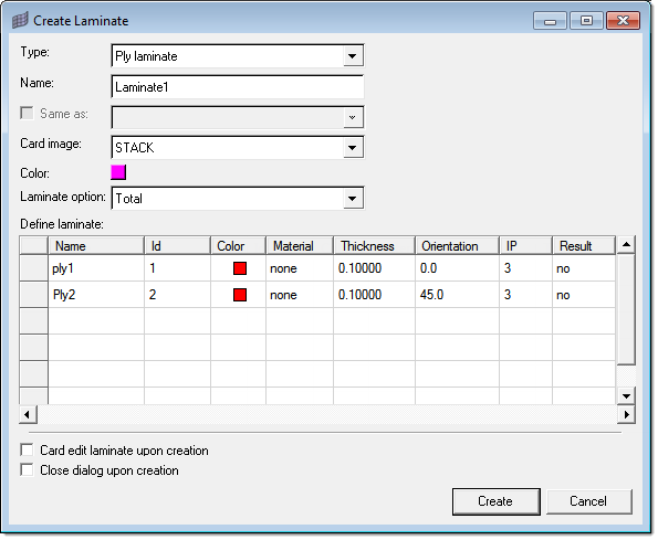
Several entry fields allow you to define the laminate's characteristics:
| 1. | Type: You can choose ply laminate, sublaminate, or sublaminate laminate. |
| • | A ply laminate is simply a laminate of multiple existing plies. |
| • | A sublaminate is similar to a ply laminate, but is created with the intention of being further incorporated into a larger laminate (the "sublaminate laminate".) |
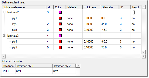
| • | A sublaminate laminate is a laminate consisting of multiple sublaminates (which in turn consist of multiple plies). |
| 2. | Name: You can type in any name for the laminate, which will then be used in browsers or whenever you need to select a laminate on a panel. |
| 3. | Same As: if you already have laminates defined and wish to create another with the same or very similar qualities, checking this option and picking an existing laminate from the list box next to it automatically fills the following characteristics to match those of the selected laminate. You can still manually edit any of the characteristics (such as the color). |
| 4. | Color: The laminate will display in this color in the graphics area, provided that you have it set to display. |
Click the colored box to open a palette and select a new color.
| 5. | Laminate option: options affect how you assemble plies or sublaminates into a laminate, or in some cases affect how a solver treats the laminate. Options include the following: |
| • | total: All plies must be specified, and all stiffness terms are developed. |
| • | membrane: All plies must be specified, but only membrane terms are developed. |
| • | bending: All plies must be specified, but only bending terms are developed. |
| • | smear: All plies must be specified, but stacking sequence is ignored by the solver. |
| • | smear core: All plies must be specified. The last ply specifies core properties and the previous plies specify face sheet properties. The face sheet properties are calculated without regard for stacking sequence; half of the total face sheet thickness is then placed on top of the core, and half is placed on the bottom, to produce a symmetric laminate. Stiffness of the core is ignored while its density is included in inertia calculations. |
| • | symmetric: Only plies on the bottom half of the composite lay-up need to be specified. These plies are automatically symmetrically reflected to the top half of the composite and given consecutive numbers from bottom to top. |
| • | symmetric membrane: Only plies on the bottom half of the composite lay-up need to be specified. These plies are automatically symmetrically reflected to the top half of the composite and given consecutive numbers from bottom to top. Only membrane terms are developed for the full laminate. |
| • | symmetric bending: Only plies on the bottom half of the composite lay-up need to be specified. These plies are automatically symmetrically reflected to the top half of the composite and given consecutive numbers from bottom to top. Only bending terms are developed for the full laminate. |
| • | symmetric smear: Only plies on the bottom half of the composite lay-up need to be specified. These plies are automatically symmetrically reflected to the top half of the composite and given consecutive numbers from bottom to top. Stacking sequence is ignored by the solver. |
| 6. | Define Laminate: For laminates and sublaminates, click in the first cell of each row in the table to reveal a list box, then use it to pick a ply. Continue specifying plies in each row until all the plies in the laminate are defined. |
For sublaminate laminates, the process is similar except that you select sublaminates instead of plies. In addition, you must right-click the table area and select add to enable the list box. Once a sublaminate is specified, a "+" sign next to it allows you to expand the entry to show the plies it contains. Finally, use a similar process to specify plies used for the interface definition.
| 7. | Close dialog upon creation (create mode only): By default, the dialog remains open so that you can create a series of laminates without needing to reopen the dialog every time. If you only wish to create one laminate at a time, activate this box to force the dialog to close when you click Create. |
When editing instead of creating a laminate, this option is not available and the dialog automatically closes upon clicking Update.
| 8. | Create or Update: creates the new laminate, or updates the existing laminate's characteristics if in edit mode. May close the dialog, depending on the dialog mode (create/edit) and the Close dialog upon creation setting. |
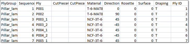
Creating New Laminates and Plies From an Excel (.csv) File
Right-click inside of the Edit Laminate dialog and select Export to csv CATIA or HyperMesh.
CATIA format:
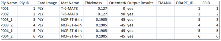
HyperMesh format:
When exporting laminate/ply data in CATIA format, this file can be imported into the CAD system (CPD) to create a composite model. You now have an alternative method to import composite data from CATIA, if the CATIA-CPD direct data import does not work.
Ply sequences can be cut and inserted after a specific ply, by right-clicking the ply and selecting Insert cut. Ply stacking sequences can be reversed if the element normal does not match the stack direction. Ply angle/orientation can also be reversed to match the element normal reversal.
See Also:
Create Ply dialog
Model browser


