Location: Model browser right-click context menu > create, or edit when right-clicking a ply.
In the Create Ply dialog, create or edit ply layers for use in laminates.
Ply shapes are based on elements or sets, therefore you must have elements or a set already defined that can be used to define the shape of the ply layer. In addition, you can assign materials when creating a ply. It is helpful to already have the relevant materials defined in your model or session. Newly created plies display in the Model browser under both Plies and Sets.
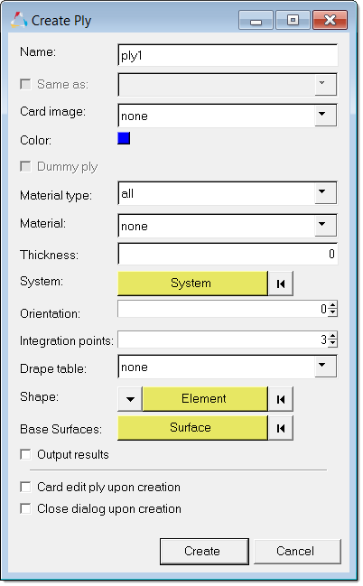
In the Create Ply dialog, define ply characteristics.
| 1. | Name. Enter a name for the ply. |
| 2. | Same As. If you already have plies defined and wish to create another with the same or very similar qualities, enable this option to select an existing ply from the list box. The remaining ply characteristics will be automatically defined to match those of the selected ply. You can manually edit any of the characteristics, such as Orientation. |
| 3. | Card image. Select a card image to assign to the ply. |
| 4. | Color. Click the color box to select a color to display the laminate in the graphics area, provided that you have it set to display. |
| 5. | Dummy ply. Select this checkbox to create a ply with zero thickness and no material to be used as separator in the stacking. A dummy ply is mainly used to group plies, which is useful when converting shell models into solids |
| 6. | Material Type. Select the type of material to display in the Material list box. |
| 7. | Material. Select a material to assign to the ply. |
| 8. | Thickness. Enter a thickness value for the ply (decimals are supported). |
This thickness value depends on the units that your model is modeled in, so it may be millimeters, centimeters, inches, and so on each of which would require a different decimal value for a ply of a given "real-world" thickness. This value can be zero, but should usually be greater than zero.
| 9. | System. Select a system to associate with the ply. |
| 10. | Orientation. Enter a degree value indicating the direction of the fibers or similar elements in the ply, using the right-hand rule based on the element normals, and using each element's material X axis as the zero degree mark. Both positive and negative values are accepted. For example, you could use 90 degrees or -270 degrees to indicate the same orientation. |
| 11. | Integration points. Enter an integer representing the number of points at which the ply is tested for failure modes. Larger numbers of integration points become CPU-intensive. A value of 3 is recommended for general usage to optimize accuracy while minimizing calculation. |
| 12. | Drape table. Select a drape table to associate with the ply. |
| 13. | Shape. Use this collector to define the shape of the ply: |
| • | Use the pulldown arrow to choose between Set and Elements. |
| • | Click the (yellow) selector to open a temporary panel. |
| • | This panel includes a collector that allows you to select the desired set or elements to define the ply shape. |
| • | Click proceed to close the temporary panel and return focus to the ply dialog. |
| 14. | Base Surfaces. Select surfaces to base ply contours/lines on. You can manually associate base surfaces to a ply, which will be used during ply realization. |
| 15. | Output Results. Writes solver results specific to this ply to the solver results file after a simulation/problem is run. |
In some cases, it is not necessary to output results for every ply. Materials with high numbers of plies can result in large result files.
| Note: | If you should later decide that ply results should have been output, you will need to change this setting for each affected ply and re-run the problem to obtain a new results file that includes the results for the affected plies. |
| 16. | Card edit ply upon creation. Opens the card editor after a ply is created. |
| 17. | Close dialog upon creation (create mode only). By default, the dialog remains open so that you can create a series of plies without needing to reopen the dialog every time. If you only wish to create one ply at a time, activate this box to force the dialog to close when you click Create. |
When using Edit mode instead of creating a ply, this option is not available and the dialog automatically closes upon clicking Update.
| 18. | Create or Update. Creates a new ply, or updates an existing ply's characteristics if in edit mode. May close the dialog, depending on the dialog mode (create/edit) and the Close dialog upon creation setting. |
See Also:
Create Laminate dialog
Model Browser


