|
»Click here to display Table of Contents«
|

Element Biasing |

|

|

|

|
|
Element Biasing |
|
|
|

|
|
»Click here to display Table of Contents«
|
Element Biasing |
|
|
|
|
|
Element Biasing |
|
|
|
|
The automeshing process enables you to bias the placement of nodes so that their intervals are not uniform in size. You can designate that the smaller intervals go near the start of the edge, near the end of the edge, near both ends with larger intervals in the middle, or near the middle of the edge.
Within the automesher, you may want to use biasing to improve element quality when transitioning from smaller to larger element sizes. When you use the Drag and Solid Offset panels, you can use biasing to cluster several layers of elements near the surface of a solid. In Linear Solids, the mesh at one end could be scaled several times larger than at the other end. Element biasing allows you to moderate the changes in aspect ratio from the start to the end.
There are three methods you can use to calculate the biasing of node positions:
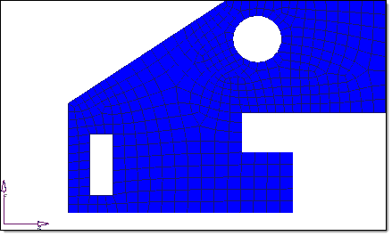
Use biasing to preserve element quality in complex regions.