Before creating a field, import the target model or analysis file that contains the new mesh into your current Engineering Solutions session.
| 1. | In the Model browser, right-click and select Create > Field from the context menu. |
| 2. | In the Entity Editor, select a field Type. |
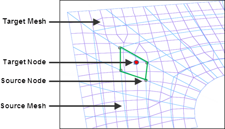
| • | Continuous fields evaluate data based on the shape function of source mesh data and its nodal or elemental values. If the location of the x,y,z points or u,v points are well structured in a rectangular array, a source mesh can be constructed. |
Source data contains the mesh and the nodal or elemental values. The target mesh is different from the source mesh.
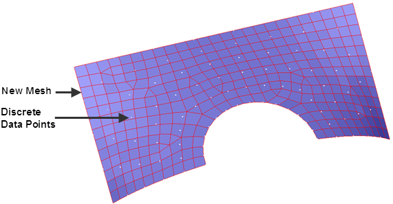
| • | Discrete fields provide data on discrete x,y,z locations (real) or u,v locations (parametric), without the source mesh. Depending on the fitness of the data points, the closest point approach or inverse distance linear interpolation method will be used to map. |
| • | Real coordinate systems (x,y,z values) |
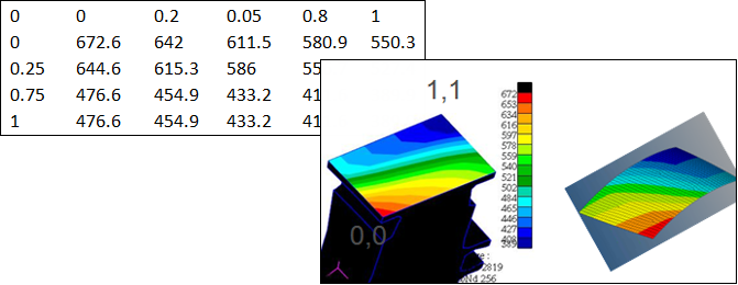
| • | Parametric systems (u,v tables) |
| 4. | Select a Source to create the field from. |
| • | results. Load an existing results file. |
| • | current model. Import an analysis data file (.bdf, .fem, .inp, and so on) and select: |
| o | pressures. Select existing pressure loads on the old mesh. |
| o | propertyid. Select existing property IDs from the current model. |
| o | materialorientation. Select existing elements from the current model based on the material angle. |
| o | valuefromfile. Select any x,y,z value file which matches the current model. The x,y,z node locations will be used, acting like the continuous field as the x,y,z location matches the old node locations. |
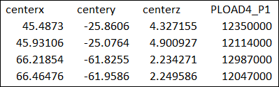
| • | csv file. Load a .csv file containing x,y,z, value1, value2 discrete data. |
| • | matrix. Load a matrix file which will be used to generate data using matrix query tools. |
|


