|
»Click here to display Table of Contents«
|

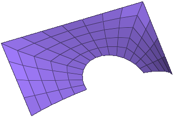
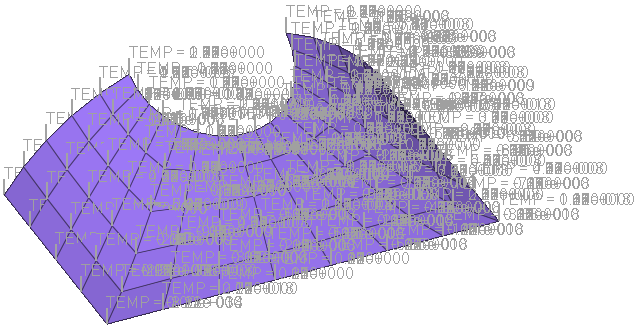
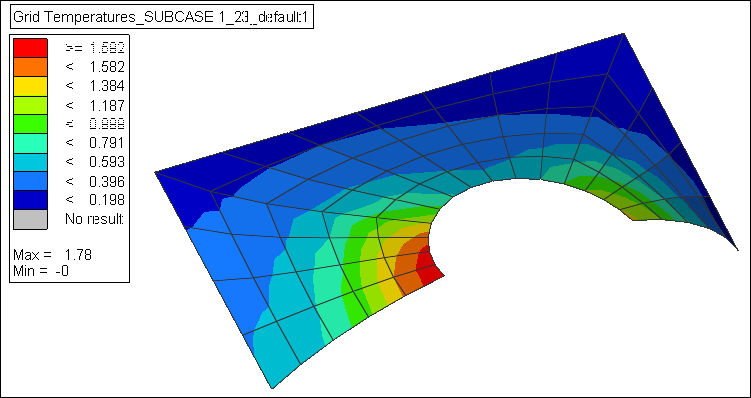
Continuous Temperature or Displacement Mapping from a Results File to a New Model |

|

|

|

|
|
Continuous Temperature or Displacement Mapping from a Results File to a New Model |
|
|
|

|