Generate BL Thickness |

|

|

|

|
|
Generate BL Thickness |

|

|

|

|
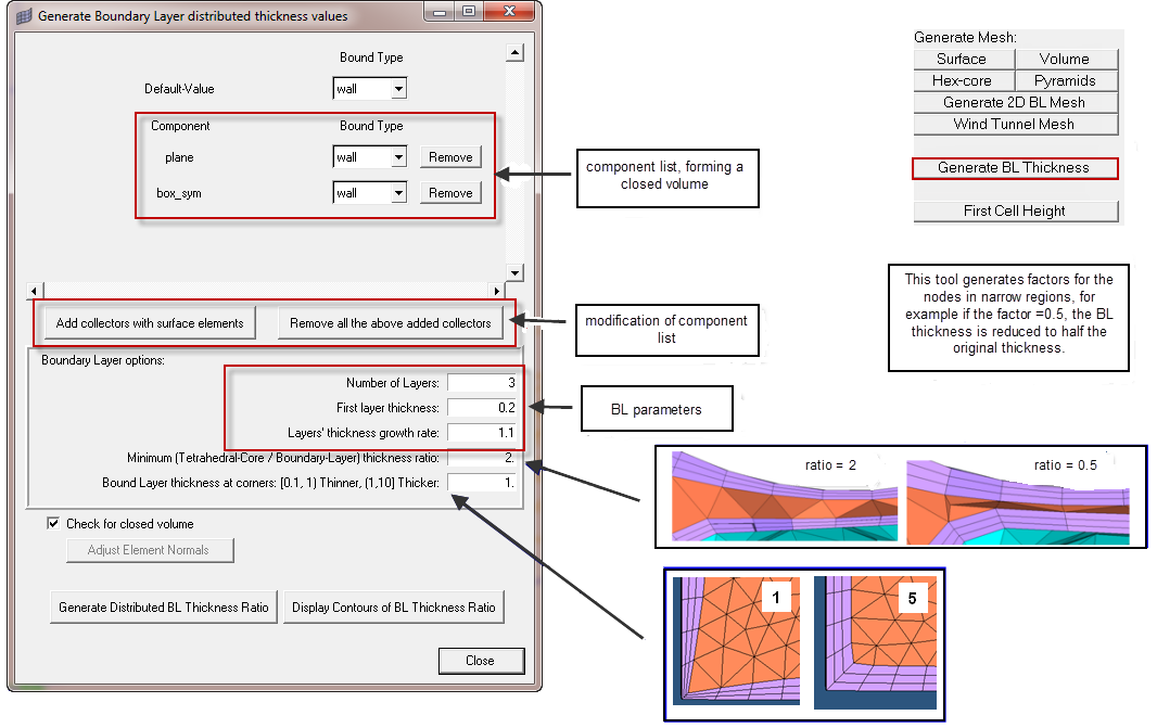
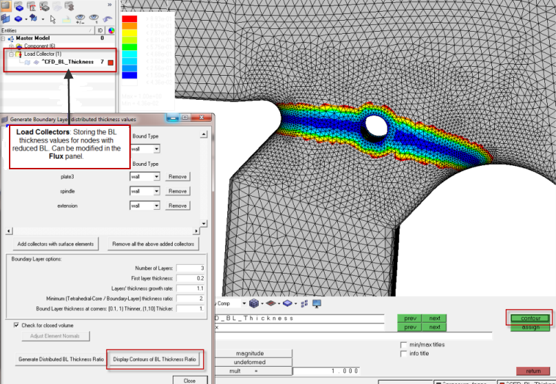
This interface is used to generate a distributed boundary layer thickness load collector named ^CFD_BL_Thickness. The goal is to reduce the total boundary layer thickness in areas where there is no room to accommodate the nominal or baseline total BL thickness. This load collector ^CFD_BL_Thickness is then used by the hex-core meshing algorithm's Distributed thickness option for surface elements on which you want to generate a boundary layer type mesh.
Click Add collectors with surface elements to define all the components containing the surface elements that define the volume to be meshed.
Next, specify Number of Layers, First layer thickness and Layers’ thickness growth rate. These values should be the same values that will be used later on in the CFD Tetramesh panel.The value of Minimum (Tetrahedral-Core / Boundary-Layer) thickness ratio is the minimum ratio between the thickness of the tetrahedral core and the boundary layer. When this value is Y, then the tetrahedral core thickness will be at least Y times the total boundary layer thickness.
The scaling Bound Layer thickness at corners is meant to reduce the total BL thickness at corners to avoid elements getting distorted or interfering with other BL elements because of the default hyperbolic growth of the boundary layer. The smaller this value, the smaller is the thickness of the boundary layer at corners relative to the nominal total boundary layer thickness.
Finally, click Generate Distributed BL Thickness Ratio. If you have a non-empty collector ^CFD_BL_Thickness, you will be prompted to select if you want to keep or discard existing distributed BL thickness values. If one node has more than one value assigned, Engineering Solutions uses the minimum value. At the end a popup message indicates the number of BL thickness ratio values generated or added to collector ^CFD_BL_Thickness. If you want to display contours of BL Thickness Ratio (rarely necessary), click Display Contours of BL Thickness Ratio.
The option Check for closed volume will check if the selected elements form a closed volume. In the case of a closed volume, the normals for BL growth is defined towards the inside of the volume. If the selected shells do not form a closed volume, this check box has to be unchecked and you have to select a normal direction with the button Adjust Element Normals, leading to the Normals panel.
|

