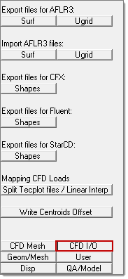
The CFD I/O Utility menu includes the following macros. Access this menu by clicking CFD I/O in the Utility menu:

Surf
|
Opens a dialog used to specify boundary collectors and meshing options for AFLR3. The first row contains default entry values (Default-Values) for AFLR3’s Reconnection, 1st-Layer thickness and for the default Boundary Type. If the value for 1st-Layer thickness is zero for all components, then the command line value associated with –blds is used. The Add collectors with surface elements button is used to add all the components containing surface elements that define the volume to be meshed. The command line options listed are saved to the shell script file used to invoke AFLR3 through the Simcenter’s aflr3 script (required to have the Simcenter installation). The same command line options are used to save a .par file that can be used with the aflr3 executable (not needing the Simcenter installation). Filenames specified by you: a .surf file containing the input boundary mesh definition for AFLR3 volume mesh generation; a .ugrid (ascii) or better a .b8.ugrid (binary) file which is the output file we are requesting to be saved when we run AFLR3; a .sh file used to invoke AFLR3 with the Simcenter’s aflr3 script with the command line options specified in this GUI; and a .par file used to invoke the AFLR3 executable directly with all the meshing options specified in this dialog.
| Note: | The *.*.ugrid filename is used in the .sh and .par files where we request the output mesh from AFLR3. The Save button is used to save the .surf, .sh, and .par files described above. Click Close to close this dialog. |
|
|
Ugrid
|
Saves a .ugrid file containing all the elements currently displayed.
| Note: | .ugrid is another format that can be used to define the input boundary mesh for AFLR3 volume mesh generation. |
|
|
|
Surf
|
Imports a .surf file. This import operation is typically used to inspect problem areas reported by AFLR3 through *.fail.surf files. When AFLR3 does not succeed in generating a mesh, AFLR3 generates a file named *.fail.surf. This file can be imported into HyperMesh to determine the region/surface area where the problem occurs. Then you can readily fix the mesh and save again input files for AFLR3.
|
Ugrid
|
Imports a binary (for example *.b8.ugrid) or ascii *.ugrid file. This operation is used to import volume meshes generated with AFLR3.
|
|
NAS Mesh
|
This utility is only available for backward compatibility; it has been superseded by save FLUENT CAS/MSH files described below. This utility exports the mesh with boundary zones (surface patches) in Nastran format (extended format to support pyramid elements). When collectors are properly named, all boundary zones are identified by FLUENT 6.2.16 with default values. FLUENT 6.3.26 does not read Nastran files with HyperMesh comments correctly, therefore it is advisable to save files in CAS/MSH format as described below.
|
Shapes
|
Exports fully functional templates for shape optimization with HyperStudy. Requires the original ascii .CAS file when exporting HyperStudy .TPL files for FLUENT. See the tutorial HS-1570: DOE and Optimization Study Using FLUENT.
|
|
NAS Mesh
|
This utility is only available for backward compatibility; it has been superseded by the utility to save StarCD Vertex-Cell files described below. This utility is used to export two files, one file contains the mesh with boundary zones (surface patches) in Nastran format (extended format to support pyramid elements). The other file is a .setup file that can be executed in pro-Star as an input file; this setup file imports the mesh file (.nas) and creates all the boundary condition zones with default settings.
|
Shapes
|
Exports fully functional templates for shape optimization with HyperStudy.
|
|
Split Tecplot files/Linear Interp
|
Utility to split TECPLOT results files written by FLUENT, StarCD, CFD++, and so on into all the solution components (present in the TECPLOT file) in a format compatible with HyperMesh’s Linear Interpolation reader. A typical TECPLOT results contains several simulation results (for example Pressure, Temperature, Velocity magnitude, and so on), one file will be created for each solution component, each file name contains a sub-string identifying the solution component. See the tutorial CFD-1700: Mapping CFD Results.
|
Write Centroids Offset
|
Saves a text file containing lines with X Y Z values corresponding to the selected elements’ centroid coordinates offset by the specified Centroid’s offset value in the direction of the elements’ normals. Only 2D elements (trias/quads) are processed. This text file is typically used by CFD solvers to save simulation values at the X Y Z locations listed in each line.
|
|
See Also:
CFD Application


