Open this dialog by clicking Auto in the 2D Boundary Layer Mesh dialog.
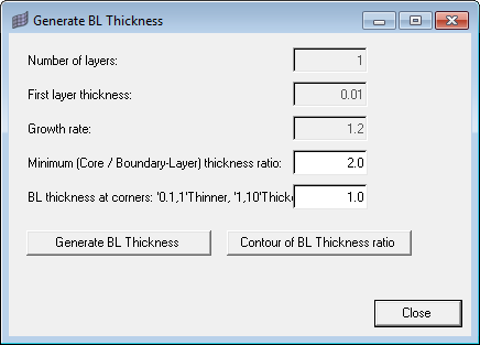
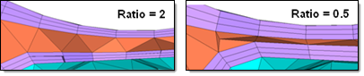
Use Minimum (Core/Boundary-Layer) thickness ratio to specify the ratio between boundary layer thickness and tetra core. This value must be more than zero, but decimal values are accepted. The higher this value, the more the boundary layer elements will be compressed to keep the core open.
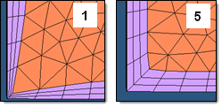
Use BL thickness at corners: '0.1,1'Thinner, '1,10'Thicker to define the boundary layer behavior in corners. The smaller this value is, the smaller the thickness of the boundary layer at corners will be relative to the nominal total boundary layer thickness. The image below shows the effects on the same model using values of one and five.
The Generate BL Thickness ratio button generates the BL thickness scaling factors to be utilized in the BL generation step.
If you wish to display contours of the Boundary Layers' Thickness Ratio, click the Contour of BL Thickness ratio button.
See Also:
Generate 2D BL Mesh


