Engineering Solutions

Tetramesh panel

Tetramesh panel

Previous topic Next topic Expand/collapse all hidden text  

Tetramesh panel

Previous topic Next topic JavaScript is required for expanding text JavaScript is required for the print function  

Use the Tetramesh panel to fill an enclosed volume with first or second order tetrahedral elements. A region is considered enclosed if it is entirely bounded by a shell mesh (tria and/or quad elements). Other element configurations generated in this panel are: hexahedral, wedge, and pyramids. These elements are typically generated when you need boundary layer type meshes on certain areas of the volume surface.


Subpanels and Inputs


The Tetramesh panel contains the following subpanels:

hmtoggle_arrow1Tetra Mesh

Use the Tetra Mesh subpanel to fill an arbitrary volume, defined by its surface using tria/quad elements, with tetrahedral elements.


hmtoggle_arrow1Tetra Remesh

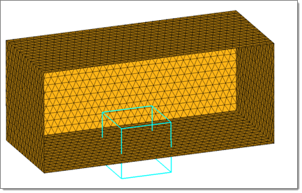
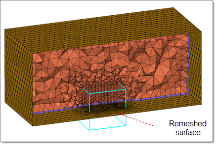
Use the Tetra Remesh subpanel to regenerates the mesh for a single volume of tetrahedral elements.

The Free boundary faces option affects those faces of tetra elements which are on the outside of the volume, meaning the tetra faces which have only one tetra attached. Those faces are called free boundary faces.

fixed: The free boundary faces are fixed.
swappable: The edges of the free boundary faces can be swapped. The mesh nodes stay unchanged.
remeshable: The free boundary faces will be remeshed.

free_boundary_faces_example

fixed

free_boundary_faces_exampe2

remeshable

hmtoggle_arrow1Volume Tetra

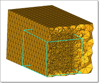
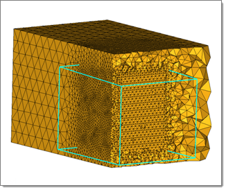
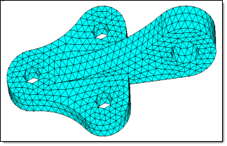
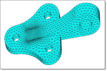
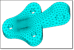
Use the Volume Tetra subpanel to generate a shell mesh and fill the enclosed volume with solid elements.

Given a solid entity or a set of surfaces representing a closed volume, this meshing option generates a shell mesh and fills the enclosed volume with solid elements. You can choose to create a shell mesh (2-D) using quads, trias, or mixed elements and a solid mesh (3-D) using tetrahedral elements only or mixed (tetras and penta) elements. In addition, you can use proximity meshing, which refines the mesh in areas where the features are small and closer together. See the following examples.

tetramesher1

Without Proximity

tetramesher1_2

With Proximity

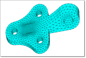
You can also use surface curvature as a function of element density as shown below. This option creates finer mesh in areas of high surface curvature.

tetramesher2

With Proximity

tetramesher2_2

With Proximity and Curvature

When you select quads or mixed as your 2D element type, Engineering Solutions creates quad elements and splits them diagonally into two trias during tetra face creation.  This can create tetra elements whose triangular faces are right triangles (90-45-45 angles) instead of equilateral triangles (60-60-60 angles).

tetramesher3

Using Triangular 2D Elements

tetramesher3_2

Using Quad or Mixed 2D Elements

Note:Sometimes the meshing may fail to correctly interpolate from the surface mesh; when this occurs, the shell elements are cleaned up according to the same settings used in the Quick TetraMesh macro on the Utility menu, and a second attempt is made. This means that some of the features in a model may be smoothed over.

Element order can be defined as first or second. Existing elements will be used if the order of the elements are the same as the defined tetramesh element order. Meshing will fail if the shell elements of solids are present and are conflicting with the selection.

If you want to apply an extra stage of calculation to improve the overall mesh quality by removing some nodes and combining elements, select the Cleanup elements checkbox.


hmtoggle_arrow1Tetramesh Parameters

Use the Tetramesh Parameters subpanel to set general qualities of the tetrameshing engine, such as a maximum element size, growth rate, the balance between speed and element quality, or whether to perform smoothing operations after initial meshing.

Note:In all cases, the meshing engine uses a minimum Jacobian element quality check value of 0.05; this can result in some nodes being moved, especially when remeshing, in order to maintain a minimum level of element quality.  When this occurs a message displays in the status bar informing you of how many mid-nodes were adjusted and saved.

Panel Inputs

Input

Action

Max tetra size

Tetra elements will not exceed this measurement in any dimension.

Optimize Mesh Quality

Directs the tetramesher to spend more time optimizing element quality. It employs the volumetric ratio, or CFD skew measurement for tetras as a quality measure. Use this option if your solver is sensitive to element quality.

TetraMesh Normally

Applies in most cases, and uses the standard tetra-meshing algorithm as in previous versions of Engineering Solutions. This option is available in each tetramesh subpanel.

Optimize Mesh Speed

Uses an algorithm for faster meshing. Use this option if element quality considerations are less important than mesh generation time. This option is available in each tetramesh subpanel.

Standard / Aggressive / Gradual /Interpolate / User Controlled/ Octree based

Affects the growth rate of elements beyond the initial uniform layers (boundary layers). These growth options control the tradeoff between the number of elements generated and the element quality.

Standard is recommended for most cases.
Aggressive generates fewer tetrahedral elements than Standard because it uses a larger growth rate.
Gradual generates more elements because the growth rate is lower than with the Standard option.
Interpolate is useful when the core mesh size should be interpolated from the surface mesh size.
User Controlled allows you to control the number of Uniform layers grown from the surface mesh and the Growth rate (which acts as an accumulative size multiplier on each layer of elements beyond the uniform layers).
Octree based is a very fast tetra mesher, and due to the logic behind this scheme, it provides a very nice BL transition.

Uniform Layers

This factor specifies how far the constant tetra size should be maintained from the surface mesh during tetrameshing. The distance is internally calculated by multiplying the user defined factor by the local surface mesh size.

HyperMesh specifies different default value of this parameter for the following growth options:

Standard:  2.0
Aggressive:  0.5
Gradual:  2.5
Interpolate:  -1.0
User Controlled: You can define your own value when you select this option.
Octree based:  2

Growth rate

The Growth rate parameter works thusly: if d is the initial thickness and r is the initial growth rate, then the thicknesses of the successive layers are d, d*r, d*r^2, d*r^3, d*r^4, and so on.

If element quality is very important and you are not concerned with the total number of elements created, then Interpolate will produce the best results because the element size changes smoothly and therefore the element quality is better.

HyperMesh specifies different default value of this parameter for the following growth options:

Standard:  1.2
Aggressive:  1.35        
Gradual:  1.08        
Interpolate:  1.08
User Controlled: You can define your own value when you select this option.
Octree based:  1.2

Pyramid transition ratio

Defines the relative height of pyramid elements used for the transition from hexa elements in the boundary layer to the tetra elements in the core.

Export settings

Save the settings to a file.

Refinement box

Specify the refinement boxes which should be considered during volume meshing. Refinement boxes not selected will be ignored.

smoothing

To apply an extra stage of calculation to improve overall mesh quality, select the smoothing check box. Additional smoothing and swapping steps will be performed and tetra elements will be split to achieve a smoother mesh transition. If tetra elements are used in the boundary layer those elements will be excluded from smoothing to maintain the original distribution.

Number of Layers

Select this check box to specify the number of tetrahedral layers to generate.

When this check box is selected, the Tetramesher ensures the tetracore contains, at minimum, the specified number of tetra layers in the model. This functionality ensures a certain mesh resolution in case of close proximity or thin channels.

When generating multiple tetrahedral layers, keep the following restrictions in mind:

Do not generate more than three or four layers, unless you refine the surfaces to have a fine mesh at close proximity areas.
Engineering Solutions will not create layer meshes near the narrow strip surfaces, as the current algorithm does not alter the surface mesh given.

fill voids

If your geometry includes volumes inside of another volume, select the fill voids check box. All volumes will be meshed.

For example if you had a sphere inside of a larger sphere, checking this option would cause the volume of the inner sphere as well as the volume between the two spheres to be meshed.

Elem quality target

You can select an element criteria and a threshold. After the tetrameshing step, Engineering Solutions will perform a mesh optimization step to fulfill the defined threshold for the selected element criteria.


hmtoggle_arrow1Refinement Box

Use the Refinement Box subpanel to define a specific box-shaped volume within an existing tetramesh in which to generate finer mesh.


Panel Inputs

Input

Action

Define refinement box: By Center and Sizes

Use the selector to pick the center node, and then use the sx, sy, and sz numeric boxes to specify the size/width of each side of the box in the x, y, and z dimensions. For instance, a size of 5 creates a 5x5x5 box centered around the center node.

Define refinement box: By Four Nodes

Use the selectors to pick a base node and three additional nodes.

These four total nodes cannot be coplanar. The base node, N1, and N2 form a triangle, which is then flipped 180 degrees to form a rectangular base for the refinement box. The vector from the base node to N3 defines the box's height and direction from this base.

Define refinement box: By Two Nodes

Use the selectors to pick nodes which represent opposite corners of a cubic volume.

Define refinement box: By Elems Box:

Use the elems selector to pick elements that define the volume, such as by means of a <shift+L-click> dragged frame.

Define refinement box: Update Refinement

Use this option to select an existing refinement box, change its Refinement size, and remesh the refinement volume.

Scaling factor

Display when the Define refinement box option is set to By Elems Box. determines the box size relative to the selected elements. A scale factor of 1 creates the smallest box that can still enclose the selected elements, while a factor of 2 creates a box twice as large in every dimension.

Refinement size

This is the target element size for mesh inside of the refinement box.

Note:The actual mesh size will vary in order to maintain mesh connectivity at the edges of the box.

In the example below, the boundary region has been selected as With BL (float) and remesh, therefore the region included in the refinement box has been remeshed with the elements size assigned to the refinement box.

remeshed_surface_example

remeshed_surface_example2

freehand edit

Opens the morphing Freehand panel. That panel allows you to alter the shape and dimensions of the refinement box to better suit your mesh.


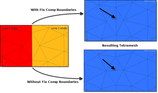
You can specify some elements to be fixed, and others to be floatable.  A fixed tria-quad element is one that must be exactly represented as a face of a tetra/penta-pyramid/hexa element in the final mesh.  A floatable element is one whose nodes locations are used, but the exact connectivity of those nodes can be modified if it produces a better mesh.  Unless you need a special mesh type (for example surface layers of pentas/hexas), you should select as fixed only those elements that must match a pre-existing mesh, leaving the rest floatable.  If the bounding surface contains quad elements, and if these quad elements are defined as fixed elements, then a first layer of elements is generated on the boundary, and pyramid elements are generated from the quad faces. However, when quad elements are defined as float elements, they are split into two trias, and the tetra meshing proceeds normally.

You can also specify various growth options in order to control the tradeoff between the number of tetras generated and their quality.  Higher, more aggressive growth rates produce fewer elements, but they may be of poorer quality.

The Tetramesh panel allows you to choose from three different mesh generation priorities.  The generate mesh normally option applies in most cases, but if your solver is particularly sensitive to element quality, use the optimize element quality option.  This directs the tetramesher to spend more time trying to generate better quality elements.  In particular, it employs the volumetric ratio (CFD "skew") measurement for rating potential tetras.  For some applications, element quality considerations are less important than mesh generation time.  In those cases, choose the optimize meshing speed option.

hmtoggle_arrow1Tetramesh Panel Functions

The following panel inputs to create a solid model of tetrahedral elements from an enclosed volume with a tria surface mesh.


Panel Inputs

Input

Action

float trias/quads

Matches the node locations of the volume elements with those of the surface mesh, but the connectivity may be modified to produce a better mesh.  Normally, this results in some tetra faces going across tria diagonals. Base quad surface elements are split into two trias

fixed trias/quads

Matches the node locations of the volume elements with those of the surface mesh.  It guarantees the connectivity of the tetras with the trias.  Use this option whenever you need to match other components to the resulting volume mesh, or when you need to generate layers composed of pentas/hexas.

fix comp boundaries

If the float option is chosen for some boundary regions, HyperMesh is allowed to swap surface shell edges during mesh generation. However, this prevents the swapping of edges between two components.

tetramesh_fix_comp_boundaries


update input shells

The shells on boundaries without boundary layers will be updated automatically after the meshing step. The updated shell elements will be placed in the initial boundary shell components.

Quad transition mode: split quads / smooth pyramid / simple pyramid

Determines how the mesher creates a transition from quadrilateral surface elements to internal tetrahedral elements:

Split quads splits the quads into trias, thus making them one face of a tetra element.
Smooth pyramid creates a boundary layer of pyramidal prism elements, and then tetrameshes the interior normally.
Simple pyramid creates pyramid elements from the quads, and then tetrameshes in accordance with each pyramid’s triangular sides.  Due to its simplicity, this option tends to produce a jagged tetramesh.

fixed with boundary layer

CFD mesh subpanel only; selects tria/quad elements that define the surface from which boundary layer elements are generated.

float w/o boundary layer

CFD mesh subpanel only; selects tria/quad elements on surfaces that do not require boundary layer elements (for example far-field, inlet, outlet, symmetry planes).

Total BL thickness /
ratio of total thickness to element size /
number of layers

CFD mesh subpanel only; determines the thickness of the boundary layer(s).

Total BL thickness allows you to specify the BL thickness, but not the number of layers.

Ratio of… is a ratio between the total boundary layer thickness and the average element size of the base surface elements.

Number of layers specifies the total number of layers to be generated using the specified first layer thickness and growth rate:

first layer thickness:  thickness of first layer of elements generated from the base surface mesh
growth rate:  Boundary layer elements thickness growth rate
acceleration: growth acceleration for boundary layers (CFD mesh subpanel’s native BL option only)
Note:The growth rate parameter works thusly: If d is the initial thickness and r is the initial growth rate, then the thicknesses of the successive layers are d, d*r, d*r^2, d*r^3, d*r^4,...

structured isotropic prisms

Applies only to the CFD mesh subpanel’s native BL option, and uses the local element size for the initial thickness and a value of 1.0 for the growth rate and acceleration.  You can use structured isotropic prism layers in any situation where ordered layers of tetras are required near the surface.  The mesher uses as many layers of isotropic elements as possible until the elements in the next layer are of unacceptable quality, and then it switches to the normal meshing algorithm.

exponential boundary layer

Applies only to the CFD mesh subpanel’s native BL option. This uses the first layer thickness, growth rate, and acceleration parameters to generate boundary layers up to a point where the thickness is of the same order as the base surface element, and then generates the remaining core with tetrahedral elements.

tetra mesh normally / optimize meshing speed / optimize meshing quality

The method of meshing optimization to use:

Tetra mesh normally applies in most cases, and uses the standard tetra-meshing algorithm as in previous versions of Engineering Solutions.  This option is available in each tetramesh subpanel.
Optimize meshing speed uses an algorithm for faster meshing.  Use this option if element quality considerations are less important than mesh generation time. This option is available in each tetramesh subpanel.
Optimize meshing quality directs the tetramesher to spend more time trying to generate high quality elements.  It employs the volumetric ratio or CFD skew measurement as a quality measure.  Use this option if your solver is sensitive to element quality.  This option is available in each tetramesh subpanel.

growth options: standard, aggressive, gradual, interpolate and user controlled

Various growth options can be specified in order to control the tradeoff between the number of elements generated and the element quality.  The standard option is recommended for most cases. Aggressive generates fewer tetrahedral elements than standard because it uses a larger growth rate, whereas gradual generates more elements because the growth rate is lower than with the standard option. The interpolate option is useful when the core mesh size should be interpolated from the surface mesh size. Lastly, the user controlled option allows you to specify the parameters to be used for the tetrahedral mesh generation.

growth rate

An option available for user controlled; this is the tetrahedral size growth rate used when filling the core volume.

initial layers

An option available for user controlled; this specifies a boundary region of d times the local surface element size where tetras should be of constant size. This value can be interpreted as the number of initial layers of tetrahedral elements generated without size correction by growth rate.