Engineering Solutions

Accels panel

Accels panel

Previous topic Next topic Expand/collapse all hidden text  

Accels panel

Previous topic Next topic JavaScript is required for expanding text JavaScript is required for the print function  

Use the Accels (accelerations) panel to create and update concentrated accelerations by applying a load, representing accelerations, nodes, components, sets, surfaces, points, or lines.

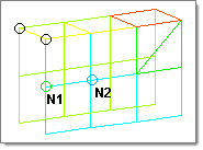
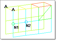
Accelerations are load config 9 and are displayed as a vector with the letter A at the tail end.

By default, accelerations are displayed relative to the model size. You can change this size by entering a different value in the relative size field. To have all loads display in the same size, use the uniform size option.

On-screen text labels of all accelerations can be removed by clearing the label loads check box.


Subpanels and Inputs


The Accels panel contains the following subpanels and command buttons:

hmtoggle_arrow1Create

Use the Create subpanel to create accelerations.


Panel Inputs

Input

Action

entity selector

Select which entities to apply accelerations to: nodes, sets, comps, points, surfs, or lines.

If accelerations are applied to nodes; this selection determines how those nodes are selected. Geometric points select the nodes at which they exist. Comps select all of the nodes contained within the chosen component.

When nodes is selected, use the switch to change the selection mode.

nodes

Select individual nodes.

faces_edges_nodes

faces

Select all of the nodes on 2D and 3D faces.

If there are discontinuities on a 2D face, then only the nodes inbetween the discontinuities will be selected.

faces_edges_faces_nodes

2D faces ext

Select all of the nodes on a 2D face that contain discontinuities.

faces_edges_2d_face_ext_nodes

loops

Select all of the nodes on continuous free edges that make a closed loop simultaneously, such as the perimeter of a hole.

Only valid for SHELL elements.

faces_edges_loops_nodes

free edges

Select all of the nodes on free edges of elements.

If there are discontinuities on an edge, then only the nodes on the free edges inbetween the discontinuities will be selected.

Only valid for SHELL elements.

faces_edges_free_edges_nodes

free edges ext

Select all of the nodes on free edges of elements that contain discontinuities.

Only valid for SHELL elements.

faces_edges_free_edges_ext_nodes

edges

Select all of the nodes on free edges or shared edges (butt joints, L/corner joints, and T-joints) of elements.

If there are discontinuities on an edge, then only the nodes on the edge inbetween the discontinuities will be selected.

Only valid for SHELL elements.

faces_edges_edges_nodes

edges ext

Select all of the nodes on free edges or shared edges (butt joints, L/corner joints, and T-joints) of elements that contain discontinuities.

Only valid for SHELL elements.

faces_edges_edges_ext_nodes

display

Indicates where in the model to draw the indicator.

Only available when the entity selector is set to comps or sets.

global system / local system

Defines an acceleration's direction relative to a local coordinate system, or the default global system.

vector

Select an existing vector entity that defines the direction of the acceleration.

curve

Select the desired acceleration curve.

Only available when magnitude= is set to curve, vector or curve, components.

magnitude =

Enter a magnitude value, and select one of the following:

constant vector
constant components
curve, vector
curve, components

N1, N2, N3

Select two or three nodes on your model to indicate the vector along which the acceleration should act.

Only available when magnitude= is set to constant vector or curve, vector.

HM_Panels_bmp00001

Before creation

HM_Panels_bmp00002

After creation

x comp, y comp, z comp

Enter the x, y, and z components of the magnitude. Only available when magnitude= is set to constant components or curve, components.

xscale =

Enter a value to alter the curve’s X scale (for example, time).

vector direction

Indicates the vector along which the acceleration should act.

relative size / uniform size

relative size = display accelerations in a size relative to the model size (default 100).

uniform size = display all accelerations with the same size.

label loads

Displays the load's text labels in the graphics area.

load types

Select a load type from the list. Available load types are defined by the user profile.

face angle / individual selection

Face angle

Value used to determine which of the selected elements are to have accelerations applied. For accelerations applied to faces, once the starting face has been identified, the normals of the adjacent remaining faces are tested. If the angle between the normals is less than the face angle, an acceleration is applied to the adjacent element. This process continues until all of the free faces have been tested. For an acceleration applied to edges, the process is similar except that the angle between edges is used instead of the angle between faces.

Only available when the entity selector is set to nodes and the selection mode is set to faces, 2d faces ext, free edges, free edges ext, edges, or edges ext.

Individual Selection

Select individual elements on a face or select individual free/shared edges of elements.

Only available when the entity selector is set to nodes and the selection mode is set to faces, free edges, or edges.

edge angle

Splits edges that belong to a given face.

When the edge angle is 180 degrees, edges are the continuous boundaries of faces. For smaller values, these same boundary edges are split wherever the angle between segments exceeds the specified value. A segment is the edge of a single element.

Only available when the entity selector is set to nodes and the selection mode is set to free edges, free edges ext, edges, or edges ext.


hmtoggle_arrow1Update

Use the Update subpanel to edit and update accelerations.


Panel Inputs

Input

Action

entity selector

Select which entities to apply accelerations to: nodes, sets, comps, points, surfs, or lines.

If accelerations are applied to nodes; this selection determines how those nodes are selected. Geometric points select the nodes at which they exist. Comps select all of the nodes contained within the chosen component.

display

Indicates where in the model you wish the indicator to be drawn. Only available when the entity selector is set to comps or sets.

global system / local system

Defines an acceleration's direction relative to a local coordinate system, or the default global system.

vector

Select an existing vector entity that defines the direction of the acceleration.

curve

Select the desired acceleration curve. Only available when magnitude= is set to curve, vector or curve, components.

magnitude =

Enter a magnitude value, and select one of the following:

constant vector
constant components
curve, vector
curve, components

N1, N2, N3

Select two or three nodes on your model to indicate the vector along which the acceleration should act. Only available when magnitude= is set to constant vector or curve, vector.

HM_Panels_bmp00001

Before creation

HM_Panels_bmp00002

After creation

x comp, y comp, z comp

Enter the x, y, and z components of the magnitude. Only available when magnitude= is set to constant components or curve, components..

xscale =

Enter a value to alter the curve’s X scale (for example, time).

vector direction

Indicates the vector along which the acceleration should act..

relative size / uniform size

relative size = display accelerations in a size relative to the model size (default 100).

uniform size = display all accelerations with the same size.

label loads

Displays the load's text labels in the graphics area.

load types

Select a load type from the list. Available load types are defined by the user profile.


hmtoggle_arrow1Command Buttons

The following action buttons appear throughout the subpanels:

Button

Action

create

Creates an acceleration.

update

Updates an acceleration.

review

Review an acceleration.

return

Exit the panel.