Use the Acoustic Cavity Mesh panel to create a fluid volume mesh for the open-air volumes of an enclosed compartment, such as the passenger compartment of a vehicle. Structural components such as seats are modeled as separate acoustic volumes. Once generated, this mesh can be used in noise/vibration testing.
Panel Usage
When generating an acoustic cavity mesh, you must first select all of the components that enclose the air spaces. You can create meshes for multiple air spaces simultaneously, depending on which components you initially select. Acoustic cavity meshing takes seating into account, and generates a separate volume mesh for each seat (bench seats are correctly treated as a single assembly, not broken up into individual seats based on the number of humans who could sit on them). This distinguishes the seats from the mesh that represents the air space.
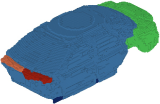
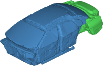
The process of creating an acoustic cavity mesh is two-staged. First, use the panel to create a voxel-based preview mesh. Second, use the browser-based Acoustic Cavity tab to select individual volumes, set element quality requirements, and create a smoother, more refined computational mesh for the selected volumes.
|

|
|
Simple preview mesh
|
|
Final acoustic cavity mesh
|
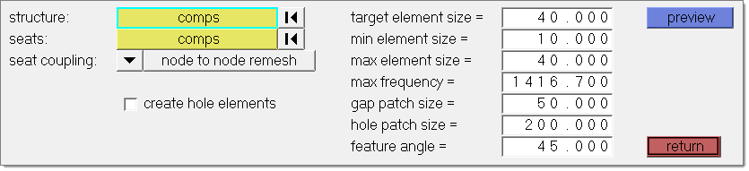
Subpanels and Inputs
There are no subpanels in the Acoustic Cavity Mesh panel. All inputs and command buttons are located on the main panel.
Panel Inputs
Input
|
Action
|
structure: comps
|
Select the components that surround the cavity.
|
seats: comps
|
Select the solid bodies representing the seats.
|
Seat coupling
|
Node to node remesh obtains new node-connected cavities for the seats, matching seat nodes, and cavity nodes on a 1:1 basis.
MPC no remesh connects the input seat components to the found cavities using MPCs, which allows node mapping at a ratio other than 1:1. Only use this option if the seat components are composed of solid elements. For proper MPC creation, the seat mesh size must be relatively similar to the size used to create the acoustic cavity mesh; in general, the size difference should be no more than 30%.
|
create hole elements
|
Creates permanent elements from the temporary elements used to patch over the holes, and stores them in their own collector called ^patched_holes.
|
target element size
|
Specify a desired element size.
Max frequency is calculated based on this target element size and number of elements per wavelength specified in Options dialog.
The actual mesh may vary from this depending on quality requirements.
|
min element size
|
Specify the minimum element size.
The acoustic cavity mesh created should not have any elements below the specified minimum element size.
|
max element size
|
Specify the maximum size of internal elements.
Max frequency is calculated based on the max element size and the number of elements per wavelength specified in the Options dialog.
|
max frequency
|
Specify the maximum frequency for which the acoustic cavity is valid for vibro-acoustic analysis.
Max frequency is automatically calculated based on the target element size and the number of elements per wavelength specified in Options dialog.
It is also possible to automatically calculate the target element size by specifying the maximum frequency.
|
gap patch size
|
Specify how large of a gap in the geometry the mesher will ignore. This value should be greater than your mesh size.
Gaps in geometry equal to or less than this size (in model units) will be patched or plastered over while the mesh is generated. Gaps larger than this will be taken into account and flooded with mesh to fill the cavities on the other side.
|
hole patch size
|
Specify how large of a hole in the geometry the mesher will ignore. This value should be greater than your mesh size.
Holes in the geometry equal to or less than this size (in model units) will be patched or plastered over while the mesh is generated. This is useful for excluding things like bolt holes. Gaps larger than this will be taken into account and flooded with mesh, which may result in bleed-through that connects different cavities of your model and treats them as a single mesh. For instance, in a passenger car you might end up with a single complex-shaped mesh that encompasses both the passenger cabin and the trunk space, with a narrow connection where a hole existed between the two otherwise separate cavities.
|
feature angle
|
Specify a feature angle.
|
Command Buttons
The following action buttons appear:
Button
|
Action
|
preview
|
Creates the voxel-based preview mesh, and opens the Acoustic Cavity tab.
|
return
|
Exit the panel.
|
| 1. | In the AcousticCavity tab, click  to open the Options dialog. to open the Options dialog. |
| 2. | Define acoustic cavity meshing parameters accordingly. |
| 3. | In the Acoustic Cavity Mesh panel, use the structure: comps selector to select the components that surround the desired cavity. |
| 4. | Using the seats: comps selector, select the solid bodies representing the seats. |
| 5. | Set the switch to node to node remesh or MPC no remesh. |
| 6. | In the target element size field, specify a desired element size. The maximum frequency will be populated automatically depending on the specified target element size and number of elements per wavelength specified in Options dialog. |
It is also possible to calculate target element size by specifying a value in the max frequency field.
| Note: | A small, fine mesh may take a considerable amount of time to generate. |
| 7. | In the gap patch size field, specify how large of a gap in the geometry the mesher will ignore. |
| 8. | In the hole patch size field, specify how large of a hole in the geometry the mesher will ignore. |
| 9. | Optional. Create permanent elements from the temporary elements used to patch over the holes, and store them in their own collector called ^patched_holes by selecting the create hole elements checkbox. |
| 10. | Click preview. A simple preview mesh is generated. |
Any further work will be accomplished in the Acoustic Cavity tab.
|


