|
»Click here to display Table of Contents«
|

Element Offset panel |

|

|

|

|
|
Element Offset panel |
|
|

|

|
|
»Click here to display Table of Contents«
|
Element Offset panel |
|
|
|
|
|
Element Offset panel |
|
|
|
|
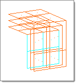
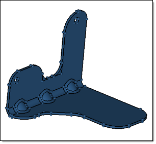
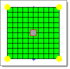
Use the Elem Offset panel to create and modify elements by offsetting from a mesh of plate or shell elements. The element normals provide directional information.
The Element Offset panel contains the following subpanels and command buttons:
Before you offset plate elements, make sure that the normals of the plate elements are properly aligned. The offset can be a negative value.
Panel Inputs
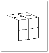
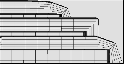
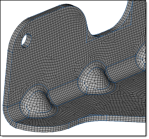
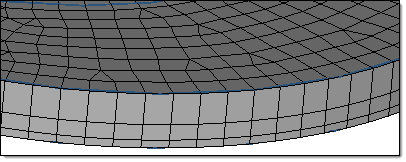
The bottom/front mesh uses rounded corners; the middle mesh uses square corners;
Comments The command function HM_COMP_TK is called to calculate each component’s thickness. This function has one argument which must be the thickness of the component. Below is an example: *components(""") *format() *variableset(variable1,$TK) *output() *return() A template that contains the HM_COMP_TK function must be specified in the user profile.
|
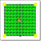
Before you offset plate elements, make sure that the normals of the plate elements are properly aligned. The offset can be a negative value.
Panel Inputs
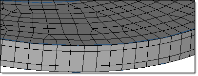
The bottom/front mesh uses rounded corners; the middle mesh uses square corners;
Comments The command function HM_COMP_TK is called to calculate each component’s thickness. This function has one argument, which must be the thickness of the component. Below is an example: *components(""") *format() *variableset(variable1,$TK) *output() *return() A template that contains the HM_COMP_TK function must be specified in the user profile.
|
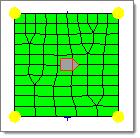
The order of the buttons, offset - and offset+, is reversed compared to the other panels to remind you that in most cases, offset - is the function to use. If you build a mesh on the surface of a CAD solid body, the elements will be aligned out of the object. So, when you use this tool to offset them to the midsurface of the solid, you will want them to go in the reverse of the element normals. This function is very similar to the Translate panel, except that instead of moving all of the elements in a fixed, uniform direction, it moves each in a direction corresponding to the local normal of the mesh in the vicinity of that element. When the selected elements are moved, entities connected to them or to their nodes, such as loads, systems, equations, or other elements, move along with them.
Panel Inputs
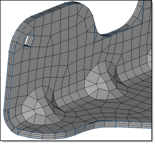
The bottom/front mesh uses rounded corners; the middle mesh uses square corners;
Comments The command function HM_COMP_TK is called to calculate each component’s thickness. This function has one argument, which must be the thickness of the component. Below is an example: *components(""") *format() *variableset(variable1,$TK) *output() *return() A template that contains the HM_COMP_TK function must be specified in the user profile.
|
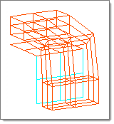
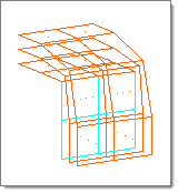
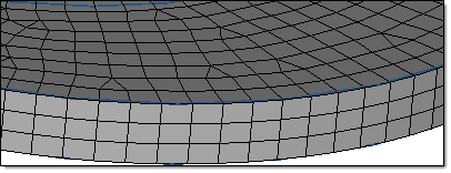
Use the Thicken Shells subpanel to convert thin shells into solid elements by making them thicker/adding a third dimension to them. When working with shells on an outer surface, you can choose the direction to extrude them; when working with shells on a midsurface, they are automatically extruded in both positive and negative normal directions.
Panel Inputs
The bottom/front mesh uses rounded corners; the middle mesh uses square corners;
Comments The command function HM_COMP_TK is called to calculate each component’s thickness. This function has one argument which must be the thickness of the component. Below is an example: *components(""") *format() *variableset(variable1,$TK) *output() *return() A template that contains the HM_COMP_TK function must be specified in the user profile.
|
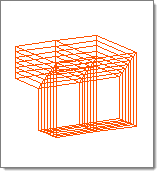
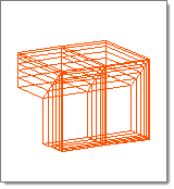
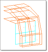
Use the Thin Solids subpanel to create thin solid meshes. The mesh is created by first generating a 2D mesh on a selected set of faces, and then extruding this mesh to generate solid hexa or wedge elements.
In order to create a thin solid mesh, the solid geometry must meet certain criteria:
Panel Inputs
|
The following action buttons appear throughout the subpanels:
|