This window compares the connectors in your model to the ones in a Master Connection File (MCF) or Master Weld File (MWF) and alerts you to any discrepancies found. Open this tool by clicking the the compare button in the Connectors module menu.
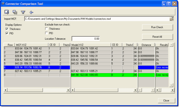
MCF connectors display on the left, model connectors on the right.
This tool displays the connectors with their thicknesses, locations, distances, and so on in two grids: one for the MCF and one for the current model. These lists of connectors are compared based on connector ID, and any connectors containing a discrepancy are highlighted. However, you can specify a location tolerance to allow for small discrepancies in connector location.
In addition, a third grid displays the difference in distance between the model’s connectors and the MCF connectors, and a fourth displays the results (pass/fail or notes/warnings).
The following table explains each of the controls in the Connector Comparison Tool window:
 (toolbar) (toolbar)
|
Export: Use this to save the comparison as a comma-separated value (*.csv) file, which can be imported into spreadsheets and similar programs.
|
 (toolbar) (toolbar)
|
Zoom: Click an entry in one of the grids and then click this button to automatically shift the graphics view to focus on the selected connector.
|
 (toolbar) (toolbar)
|
Filter: This button hides all connector entries in the grids except for errors and any entry that you have specifically highlighted.
|
 (toolbar) (toolbar)
|
Show All: Removes any filters previously applied.
|
Import MCF:
|
Either type in the path to the Master Connection File or Master Weld File that you wish to compare the model to, or else click the browse (open-folder) button at the end of the text field to browse to and select the file.
|
Thickness
|
When this checkbox is active, a column to display each connector’s thickness appears in both the MCF and Model grids.
|
PID
|
When this checkbox is active, columns displaying the Part ID of each connector’s attached components appear in the MCF and Model grids.
|
Exclude from run check:
|
Use the checkboxes provided to ignore thickness discrepancies, and/or ignore the PID numbers of the components attached to each connector (relying instead purely on the connectors’ X,Y,Z values to determine discrepancies) when comparing connectors.
|
Location tolerance:
|
Connectors whose locations don’t match between model and MCF but in which the discrepancy is this distance or less won’t be flagged as errors.
|
Run Check
|
After you have specified an MCF or MWF file and the desired thickness and PID criteria, click this to run a comparison between the model’s connectors and the ones listed in the MCF/MWF file.
|
Reset All
|
This button clears the grids and resets the checkboxes and Location Tolerance to their default states (does not clear the MCF file path).
|
Close
|
Close the comparison tool window.
|
See Also:
Connectors Module
Alphabetical List of Panels


