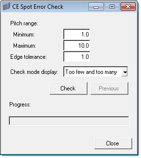
Use this tool to run an error check on all or selected components, to determine if a component has potential error in the spot weld connectivity. Open it from the Check sub-menu.
The Spot Error Check tool's purpose is to:
| • | Find comps that are not connected to anything. |
| • | Check number of spot welds per comp: user supplies ideal weld pitch range (for example 30 - 80mm) |
This tool calculates the perimeter of each pshell component, then divides by the number of connectors attached to that comp. Anything outside the threshold is failed and flagged for you to investigate. This helps to find missing welds or components with too many welds.
This tool calculates how many realized connectors are within a specified Edge Distance from the edge of a given component. It only checks for errors in spot weld connectivity--it does not check for equal spacing of connectors along an edge, but instead uses the previous information to calculate the average pitch range.
If the average pitch range is between the Min and Max inputs, the given component passes the error check and is not shown. If the calculated pitch range lies outside is the Min and Max inputs, the component may be shown as having an error (dependant upon what the Check Mode Display option is set to).
Much of the tool's behavior depends on the option chosen for Check mode display, which refers to the number of connectors found compared to the specified Pitch range.
| • | Too few: With this option all the components which are not connected to anything (or for which the pitch value is greater than your specified the Maximum Pitch Range) are displayed in the graphics area. |
This refers to the components which contain fewer links to other components than the Pitch Range value you specified. These components and the connectors are considered to be failed and should be investigated.
| • | Too many: With this option, all the components for which the Pitch value is lesser than the specified Minimum Pitch range value are displayed in the graphics area. |
This refers to the components which contain more links to other components than than the Pitch Range value you specified. These components and the connectors are considered to be failed and should be investigated.
| • | Too few and too many: The tool displays all the components that contain fewer realized connectors than the minimum Pitch range value as well as the components that contain more realized connectors than the maximum Pitch range value. |
To run a check, specify the criteria you wish to use (minimum and maximum pitch, edge tolerance, and check mode display) and then click Check. Once a check has been run, you can also use the Previous button to review the previous results.
Test Examples
In this example, a model contains 12 connectors which are each linked to comp1 and comp2. The outer border of each component is 160 units. This means the average pitch distance between each of these connectors (on comp1 and comp2) is 13.33 units (160/12).
Given these characteristics, the following tests should yield the results indicated for each:
Tests
| 1. | Min 10; Max 15; Edge Distance 1; mode too many: |
| • | Looking for at least of 10.6 connectors (160/15) but not more than 16 connectors (160/10) on each part edge. |
| • | Output: Should show nothing; no component more than 16 connectors on each part edge. |
| 2. | Min 10; Max 15; Edge Distance 1; mode too few: |
| • | Looking for at least of 10.6 connectors (160/15) but not more than 16 connectors (160/10) on each part edge. |
| • | Output: Should show comp3 which has no connectors--thus, too few connectors (fewer than 10.6). |
| 3. | Min 0; Max 10; Edge Distance 1; mode too many. |
| • | Looking for at least 16 connectors (160/10) but not more than infinity (160/0) on each part edge. |
| • | Output: It is impossible to have more than infinity connectors (too many), so this should show nothing (empty screen). |
| 4. | Min 0; Max 10; Edge Distance 1; mode too few. |
| • | Looking for at least 16 connectors (160/10) but not more than infinity (160/0) on each part edge. |
| • | Output: Should show comp1, comp2, and comp3 (because all 3 have fewer than 16 connectors on them). |


