|
»Click here to display Table of Contents«
|

Hole Detection Tool |

|

|

|

|
|
Hole Detection Tool |
|
|

|

|
|
»Click here to display Table of Contents«
|
Hole Detection Tool |
|
|
|
|
|
Hole Detection Tool |
|
|
|
|
Use the Hole Detection tool to locate many holes in a model (and potentially all of them), define them, and add those holes as geometry to a new component or to the current one. You can specify many types of criteria to define specific types of holes that you wish to find.
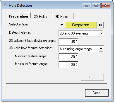
The tool includes three tabs: Preparation, 2D Holes, and 3D Holes.
In the Preparation tab:
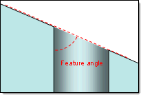
Holes in 3D solids are assumed to have an opening on one or more faces of the solid. You can base detection on each hole's feature angle, that is, the angle at which the hole deviates from the face in which its opening appears.
Use the 3D solid hole feature detection list box to select a method of specifying the feature angle.
In either case the values must be more than zero (zero would be perfectly collinear with the face) but no greater than 90 degrees (which represents a hole that runs perfectly perpendicular to the face). Once you select entities and determine the element types and feature angles to search for, click run to perform the scan. Once the scan is complete, the 2D Holes and 3D Holes tabs become enabled.
|
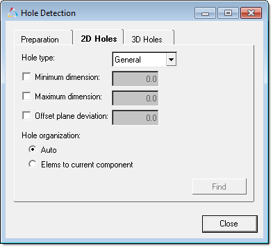
In the 2D Holes tab, refine the types of holes you wish to find in 2D mesh.
The hole type refers to the 2D shape of the opening: circular (including ovals), square, or rectangular. The general option includes all shapes. Minimum and Maximum dimension refers to the width of the hole, regardless of shape. If set at or below zero, these checks are not run.
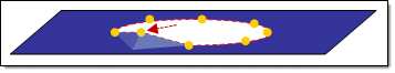
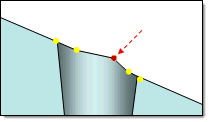
Offset plane deviation checks each node on the edge of a hole, relative to the plane that best approximates all of the nodes on the hole's edge. This is a distance measurement; any nodes further than this distance from the midplane of the bounding box will cause the tool to ignore the hole. If this value is set to zero or less, the check is not run at all on any holes.
In this image, the raised node might invalidate the hole. The Hole organization options control which component the found holes are placed into: by default they are added to a new component called ^edges_holes_shell. However, you can force them all to be placed into the current component instead. Once you are satisfied with your settings, click Find. All 2D holes matching the criteria are located.
|
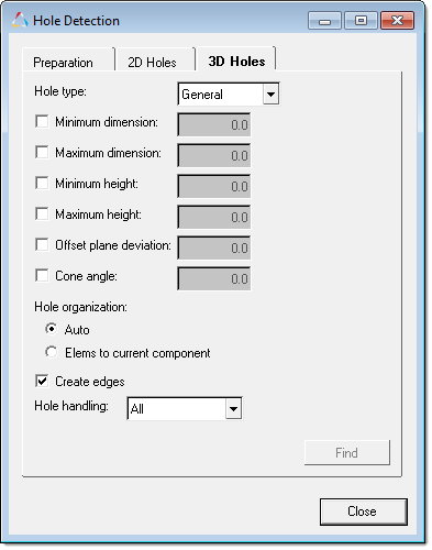
In the 3D tab, refine the types of holes you wish to find in 3D mesh to greater detail.
The Hole type refers to the shape of the opening: circular, square, or rectangular. The General option includes all shapes. Minimum and Maximum dimension refers to the width of the hole's openings, regardless of shape, and carries over from the 2D page because the openings themselves are 2D edges. If set at or below zero, these checks are not run.
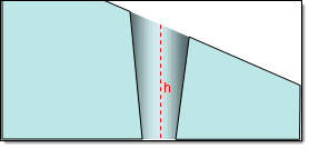
Minimum and Maximum height refers to the depth of the hole, regardless of shape. If set at or below zero, these checks are not run.
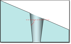
Offset plane deviation checks each node on the edge of a hole, relative to the best-fit bounding box that encompasses all of the nodes on the hole's edge. This is a distance measurement; any nodes further than this distance from the midplane of the bounding box will cause the tool to ignore the hole. If this value is set to zero or less, the check is not run at all on any holes.
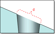
With very low plane deviation, the red node might invalidate this hole. Cone angle searches for specific tapered holes; this is the maximum angle between the hole's sides, and a planar cross-section that is perpendicular to its length.
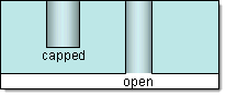
Thus, a value of 90 represents a hole that does not taper at all. Holes with a taper at or below the specified angle (that is, tapers sharper than the specified angle) will be found, while tapers above it (that is, closer to being a straight shaft) will be ignored. The default value is 80.0 degrees; if less than or equal to 0.0 the cone angle check is not run. The Hole organization options control which component the found holes are placed into: by default they are added to a new component called ^edges_faces_solid. However, you can force the shell hole elements to be placed into the current component instead. If you activate the Create edges option, the tool will generate elements around the perimeter of the hole edge– these new elements are organized into a component called ^edges_holes_shell. Use Hole handling to determine whether to find Open holes, Capped holes, or All holes.
Once you are satisfied with your settings, click Find. All 3D holes matching the criteria are located.
|
See Also: