From the Thickness Output section, define thickness output. Click Calculate Thickness to begin the operation. The thickness will be computed and assigned on the mid-mesh.
Select one of the following thickness output options:
Output
|
Description
|
User Profile
|
Node
|
Assigns a thickness on node cards.
|
Abaqus
|
Element
|
Assigns a single thickness on element card.
|
RADIOSS, Abaqus, LS-DYNA, PAM-CRASH2G (TSHELL and SHELL card image)
|
Nodal Thickness on Elements
|
Assigns multiple thicknesses on elements for each node.
|
OptiStruct, LS-DYNA, Nastran
|
Properties on Elements
|
Creates properties for groups of elements, and assigns a thickness to each property.
|
OptiStruct, Nastran, Abaqus
|
Properties on Components
|
Creates components and properties for groups of elements, assigns a thickness to each property, and then assigns the property to a component.
|
LS-DYNA
|
Select Card Image
|
Assigns a thickness on INISHE entities, when you select one of the following card images from the list: SHELL, EPESP_F, STRA_F, and STRS_F.
|
RADIOSS
|
Thickness on Components
|
Assigns thickness on PART (SHELL, TSHEL, and MEMBR)
|
PAM-CRASH2G
|
Contact Thickness on Components
|
Assigns contact thickness to TCONT on PART (SHELL, TSHELL, and MEMBR)
|
PAM-CRASH2G
|
|
Specify a minimum thickness to assign calculated thicknesses below the specified value.
|
Specify a maximum thickness to assign calculated thicknesses above the specified value.
|
Assigns an offset value to element cards.
Note that the mesh deviates from the geometry; the mid-mesh node is equidistant from mesh corners, but not from
the nodes on the geometry corners.
- 2D Detailed Element Representation is active
- No Element Offset is active
Here, the offset has caused the mesh to match the geometry, though the initial mid-mesh node remains unchanged.
such that it now matches the geometry.
- 2D Detailed Element Representation is active
- An Element Offset is active
|
Approximates the thickness values on individual elements to be an average value representing a group of elements.
Only available when thickness output is Elements.
|
Controls the number of thickness properties or groups. Enabling this option ensures that no thickness group or property will have a thickness interval range greater than the specified value. In other words it is the maximum limit on the max thickness – min thickness in a thickness group or property.
Selecting Abs (absolute) groups thicknesses in the given intervals; selecting Rel (relative) calculates the absolute thickness interval value by multiplying the given value with the average thickness of the group (that is, the given value is the ratio of the interval value to the average thickness of the group).
Only available when thickness output is Properties on elements or when Assign average thickness to element groups is selected.
|
Rounds the thickness values up or down to have the same number of decimal digits as the input value in the Maximum thickness range interval field.
Only available when Maximum Thickness Range Interval is selected.
|
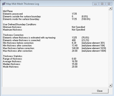
The information logged during the computation can be directed the supplied file.
|
Advanced Options
On elements or nodes where the thickness could not be computed correctly, there are different options to correct it:
| • | Interpolate from Neighbors: An appropriate thickness value is interpolated from the neighboring element/node thickness. |
| • | Adjust to min/max values: If either minimum or maximum thickness is defined it is assigned on the corrected elements. |
|
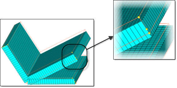
Applies a scaling algorithm when interpolating thickness values near t-junctions or corners.
| • | Supplying a value less than 1 will result in linear decrease in the thickness values nearer to the junctions / corners. |
| • | A value of zero will result in an approximate mass-conserved thickness estimation. |
|
|
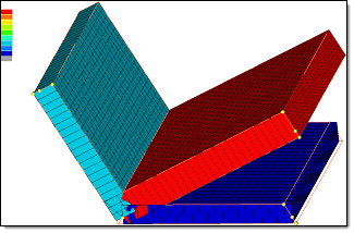
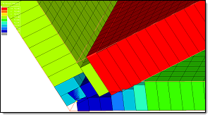
Scaling at corners = 0
Thickness Contour Applied
Traditional Element Visualization
|
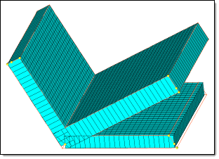
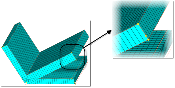
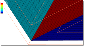
Scaling at corners = 0
Thickness Contour Applied
2D Detailed Element Representation
|
When equal to 1, the thickness is extrapolated / interpolated without any scaling.
|
|
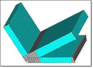
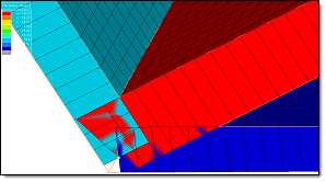
Scaling at corners = 1
Thickness Contour Applied
Traditional Element Visualization
|
Scaling at corners = 1
Thickness Contour Applied
2D Detailed Element Representation
|
When greater than 1, the thickness will increase as you go closer to the junction.
Only available when the Correction method is set to Interpolate from Neighbors.
|
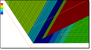
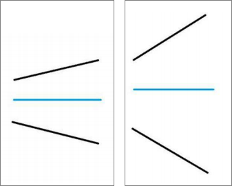
Defines the cut-off angle in degrees.
Enter the maximum angle (0 to 90) that the mid-mesh makes with the solid, beyond which the estimated thickness will be ignored and corrected.
For example, the images below show the midmesh in blue, and the solid in black. In the first image the midmesh and the solid form a moderate angle. However in the second image the midmesh and the solid form a larger angle. It is possible that this area is a junction, located at the solid edge, or the solid may contain some noisy features, therefore you may want to ignore the calculated thickness and interpolate that value from surroundings.
|
Measures the change in adjacent thickness values, and restricts the gradient.
Enter the maximum change in thickness allowed across two adjacent measurement locations, as a factor of the distance between the locations. Allowable factors range from 0 to 10.
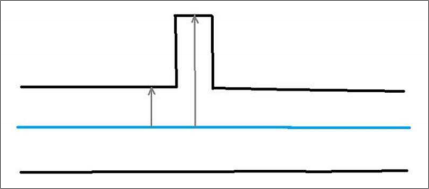
For example, the image below shows a tiny projected boss in an otherwise planar area, which you may want to ignore. Defining the Max thickness gradient specifies the cut-off for the ratio of difference in thickness at two locations to the distance between the two locations. If the ratio is more than the given value, the measured thickness is discarded, and interpolated from its neighbors.
|
Specify a maximum relative faceting error to use during faceting calculations.
When HyperMesh computes the proximity with a solid, it do not actually compute with the surface geometry. Instead, HyperMesh computes with the tessellated approximation (facets) of the geometry. In case of curved geometry, the facets may not exactly match the geometry, and hence the thickness is computed, causing faceting errors. Specifying the Max relative faceting error enables you to control the accuracy of the tessellation used, as a factor of the estimated thickness. The Max relative faceting error is the ratio of the maximum error of facets to the estimated thickness. If it exceeds this value, facets are further refined to better capture the geometry.
|
Specify the maximum distance which will be considered for searching solid proximity. This value is also used to restrict the maximum distance from which a good thickness value is considered for correcting an incorrect thickness estimate. You can also used this option to restrict the algorithm from assigning incorrect thicknesses for the mid-mesh that is out of the solid proximity.
|
When this option is enabled, a thickness will not be assigned to the Mid-mesh outside of the solid.
|
|