The Link Entity browser is a tool to easily examine the connections between the different parts of a model. One strategy to do that is to start the investigation on one part or a certain group of parts, so each action in the Link Entity browser starts with a selection of parts. Parts can be considered as links.
These view options affect the Link Entity Browser action modes tools, and thus determine the entities that display when you select and then show, hide, or isolate a link.
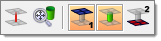
Each button is modal--that is, you click it once to activate it, and click it again to deactivate it. Active buttons remain active until you specifically deactivate them, so you do not need to worry about them "resetting" after you perform an action such as isolate.

active
|

inactive
|
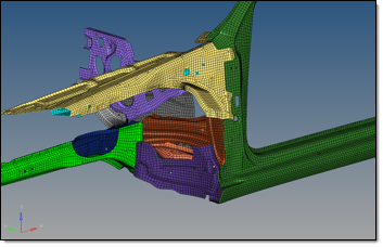
The following model illustrates the effects of these search options.
| Note: | The highlighted component; this component is the starting point for the following examples. |
|
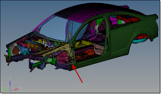
(Model provided courtesy of Audi)
In each example below, the selected component has been isolated, using only the relevant view option.
Option
|
Name
|
Effect
|
|
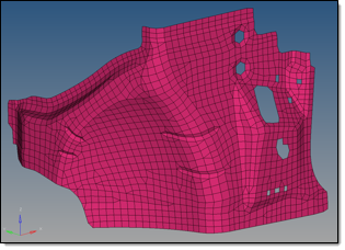
1st link entity
|
The selected link entity can always be seen as the 1st link entity, even if the selected part is not referenced by any connector at all. If the 1st link entity view option button is active, the selected links will be taken into account for the action regardless.
This means that in case of the isolation, all selected links will be isolated.
|

|
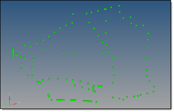
Linked connector entity
|
If this linked connector entity view option button is active all connectors linked to the 1st link entities will be taken into account for the action. It does not matter if the 1st link entity view option button is active or inactive, its connectors will still be located (this determination has nothing to do with any display states).
This means that in case of the isolation, only the connectors which are referenced by the selected links (1st link entity) are isolated.
|

|
2nd link entity
|
If the 2nd link entity view option button is active, all link entities referenced by the determined connectors except the (selected) 1st link entities will be taken into account for the action. It does not matter if the 1st link entity or the linked connector entity view option buttons are active or inactive; this determination has nothing to do with any display states.
In the case of isolation, this means that only the links that share connectors with the selected entities are isolated.
The selected link is hidden because 1st link entity was not active
|

|
Realization
|
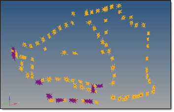
When this option is active, all realizations belonging to the determined linked connector entities will be taken into account for the action.
|
Cumulative Effect of Multiple Options
These options work accumulatively--for example, when both the 1st link entity and 2nd link entity buttons are active, then selecting and isolating a component link displays both it and all of the components connected it. If you had realization, 1st link entity, and 2nd link entity active when you isolated the same component link, then the model would display all of the component links connected to the selected one, as well as graphical representation of the realizations of each connector linking those component links together.
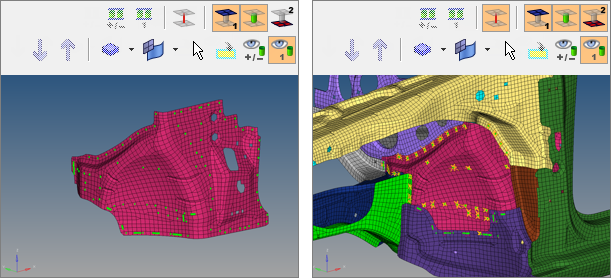
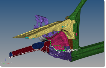
The first image shows an isolated view with only 1st link and connectors. The second includes 1st and 2nd links, connectors, and realizations.
Using the 2nd Link Option to Expand the Selection
You can use the 1st link and 2nd link options together to gradually add more and more links to your viewable model by starting with a small area, such as a single supported entity, and then selecting additional supported entities. The example below starts with a single component that has been isolated using the 1st link and linked connector entity options. Then, using the 1st link, linked connector entity, and 2nd link options, the Show action mode tool is activated. In each subsequent image, one component (highlighted) is selected to be shown. Because the 2nd link option is active, all components connected to the selected one are revealed.
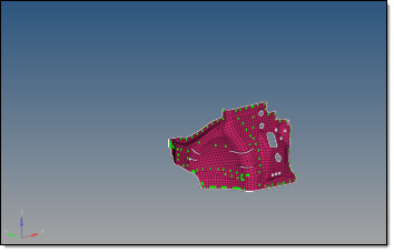
Here, the initial isolated component has been selected
All entities attached to the component are revealed. Another is selected.
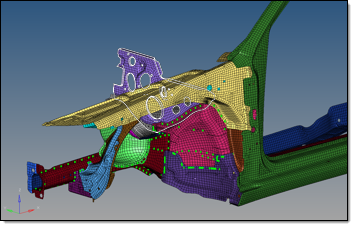
Again, link entities attached to the selected one are revealed. A third is selected.
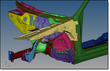
And still more entities, having no direct connection to the original part, display.


