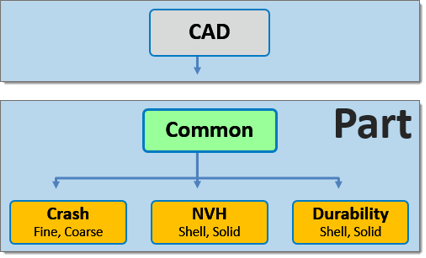
A part can contain multiple representations. The CAD representation forms the basis of the Common representation, which in turn is the basis of all subsequent discipline specific mesh representations. This hierarchical relationship is shown in the image below. The Common representation component typically contains geometry, though it can also consist of FE mesh. For more information on common and discipline specific mesh representations, see Part Representations.
A folder based Representation repository stores all CAE data that is required during the model build and assembly process. CAE data stored in the Representation repository includes the geometric and FE representation of the parts that comprise the subsystem specific model hierarchy.
You can import a BOM via a neutral file format such as PLMXML or manually create a part structure using the Part browser context menu.
Part representations can be created in the Change Representation dialog, Create tab. Representations utilize the mesh parameter and criteria files that are included with Engineering Solutions. You can find these files in the BatchMesher. The Param File and Criteria File fields display the representation specific mesh parameter and criteria file.
Common representations form the basis of all subsequent discipline specific mesh representations. When you select a discipline specific mesh representation from the Change Representation dialog, Create tab, the Common representation residing in the repository is automatically sent to the BatchMesher for processing. If the Common representation does not exist it will be automatically generated.
| 1. | In the Part browser, right-click on part assemblies or parts and select Representations > Create from the context menu. |
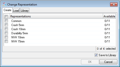
| 2. | In the Change Representation dialog, Create tab, select a desired representation. |
The availability of the selected representation in the repository is displayed next to the representation type within parentheses. In the image below there is (0/11) common representations available in the repository.
| 3. | Optional. To save the newly created representations to the Part Library select the Save to Library checkbox. |
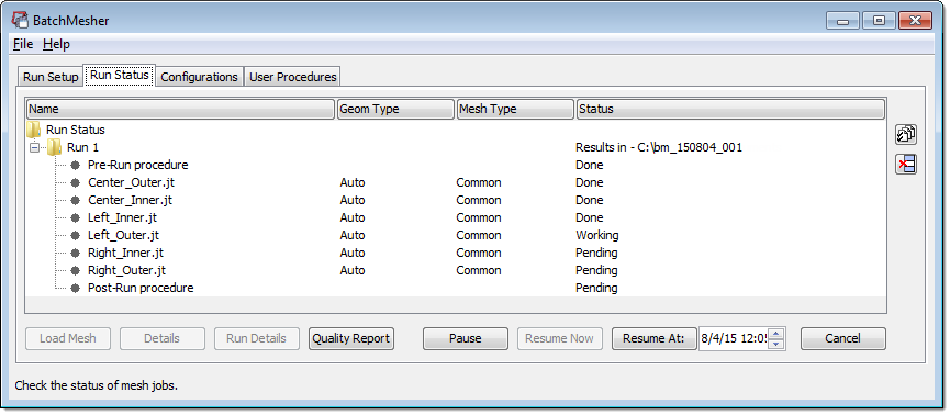
| 4. | Click OK. All representations are sent to the BatchMesher for processing in parallel. Upon completion, all representations are automatically saved to the repository. |
| 5. | In the BatchMesh dialog, click Yes to import all representations into the session or click No to not import the representations into session. If you click No, the representations will be available in the Load Representation dialog. |
|
Create your own user defined representation. User defined representations are saved to the settings and will be available in subsequent HyperMesh sessions.
| 1. | In the Part browser, right-click on part assemblies or parts and select Representations > Settings > User Representations from the context menu. |
| 2. | In the User Representations dialog, click + to add a new representation. |
| 3. | In the Representation field, enter a name for the representation. |
| 4. | In the Param File and Criteria File fields, select the appropriate mesh parameter and criteria file. |
|
Part representations can be added from external sources such as solver decks and Engineering Solutions binary files or from the Part Library.
Adding Representations for a Single Part from External Sources
| 1. | In the Part browser, right-click on a part and select Representations > Add > from Files from the context menu. The Add Representation dialog opens. |
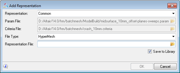
| 2. | From the Representation field, select a desired representation type to which a representation file will be added or add your own user defined representation by typing a string into the field. If you added your own representation, select the appropriate mesh parameter and criteria files. |
User defined representations with defined mesh parameter and criteria files created in the Add Representation dialog will be available in the Change Representation dialog, Create tab. User defined representations with undefined mesh parameter and criteria files created in the Add Representation dialog will not be available in the Change Representation dialog, Create tab, but will appear in the Load tab if a representation is found in the repository.
The availability of the selected representation in the repository is displayed next to the representation type within parentheses.
| 3. | Optional. To save the representations to the Part Library select the Save to Library checkbox. |
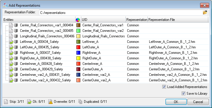
Adding Representations for Multiple Parts and Part Assemblies from External Sources
When selecting a part assembly or multiple parts, the Add Representations dialog enables you to map and associate representation files to multiple parts simultaneously.
If appropriate metadata is available in the BOM, then the alias values will be preselected. After choosing a Representation Folder, representation files will be mapped according to the HyperMesh naming convention. You can then manually select or update any of the alias and representation file values.
Indicators are displayed for each part to indicate the status of that row.
| • | Skip. Any Part which does not have a mapped or selected representation. |
| • | OK. Alias and representation are chosen for the part. |
| • | Overwrite. Part already has a representation which will be overwritten by the selected mapping. |
| • | Duplicated. The same representation file is chosen for more than one part, or the chosen representation file is already used by another part in the same BOM. You cannot click OK to add the representations when representations are duplicated. |
| 1. | In the Part browser, right-click on part assemblies or multiple parts and select Representations > Add > from Files from the context menu. |
| 2. | In the Add Representations dialog, Representation Folder field, navigate to the representation file. |
| 3. | Select the parts you would like to map and associate with the representation file. |
| Note: | You cannot add CAD or connectors. |
| 4. | Optional. To save the representations to the Part Library select the Save to Library checkbox. |
|
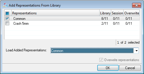
| 1. | In the Part browser, right-click on a part/part assembly and select Representations > Add > from Library from the context menu. |
| 2. | In the Add Representations fro Library dialog, select representations to add. |
| 3. | Optional. To simultaneously add and load representations, select representations to load from the Load Added Representations list. |
|
After importing a BOM, you can add CAD representations to the Part Library.
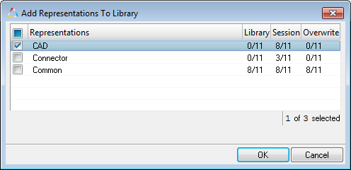
| 1. | In the Part browser, right-click on a part/part assembly and select Representations > Add > to Library from the context menu. |
| 2. | In the Add Representation to Library dialog, select representations and click OK. |
The Add Representation to Library dialog displays information regarding the availability of representations in library, session, and overwrite details.
In the example below, CAD representations are being added to the Part Library. The Library column displays 0/11, which indicates there are no CAD representations available in the Part Library. The Session column displays 8/11, which indicate 8 out of 11 representations are currently available in the active HyperMesh session. The Overwrite column displays 0/11, which indicates none of the representations will need to be overwritten.
|
|
Part representations can be loaded from your current Engineering Solutions session or from the Part Library.
| 1. | In the Part browser, right-click on part assemblies or parts and select Representations > Load > from Session from the context menu. |
| 2. | In the Change Representation dialog, Load tab, select a type of representation to load. |
Representations that exist in the repository are shown in the Representations column, and their availability is indicated in the Available column.
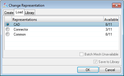
| 3. | To send unavailable representations to the BatchMesher directly from the Change Representation dialog, select Batch Mesh Unavailable. |
| Note: | Available representations will also be loaded when you click OK if Batch Mesh Unavailable is selected. |
| 4. | Optional. To save the representations to the Part Library select the Save to Library checkbox. |
| 6. | In the Confirm Load Representation dialog, click: |
| • | Load All. Loads all available representations into the current session for selected parts. |
| • | Skip Loaded. Ignores representations that are already loaded for selected parts. |
As representations are created and saved to the repository they are displayed in the Available Representations pane.
|
After importing a BOM that has representations saved in the Part library, you can load the saved representations.
| 1. | In the Part browser, right-click on a part/part assembly and select Representations > Load > from Library from the context menu. |
| 2. | In the Change Representation dialog, Library tab, select representations and click OK. |
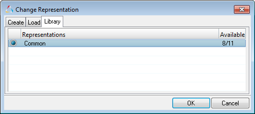
The selected representations are loaded to the Representation folder on the file system. Similarly, every time a BOM is imported, files are loaded to the Representations folder, if you retrieve them from the Part Library.
|
|
Part representations can be restored to their original state by right-clicking on parts or part assemblies and selecting Representation > Reload from the context menu. Representations are reloaded from the repository.
|
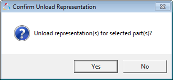
Part representations can be unloaded from a session by using the Unload Representation function.
| 1. | In the Part browser, right-click on the Model, part assemblies, or parts and select Representation > Unload from the context menu. |
| 2. | In the Confirm Unload Representation dialog, click Yes to unload the selected representations. |
|
| 1. | Select a part or parts to update, then right-click and select Representations > Update from the context menu to: |
| • | Rename the selected parts or part's component (or create if it does not already exist). |
| • | Create a material based on PDM Material and PDM MID. |
If a material of the given ID already exists, then it will not be overwritten or recreated in order to avoid overwriting any existing material properties.
Only linear attributes are updated. Default steel attributes are used with the following unit system: millimeter, second, tonne, and Newton.
| • | Create a property based on PDM PID and PDM Thickness*. |
If a property of the given PID already exists, its thickness will be updated based on PDM Thickness; however, the existing property will not be recreated. Only relevant metadata will be updated in order to avoid overwriting any existing property card values.
*If the PDM MeshFlag attribute is set to SMT (Solid Mesh Tetra) or SMH (Solid Mesh Hexa), than a solid card image will be assigned to the property.
|
Sync PDM metadata (PDM PID, PDM Thickness, PDM Material, and PDM MID) based on a selected part or part's metadata (PID, Thickness, Material, MID) by right-clicking on a selected part or parts and selecting Representations > Sync Metadata from the context menu.
*When a part has multiple properties, only the first property will display in the PID PDM field when you select Sync Metadata.
|
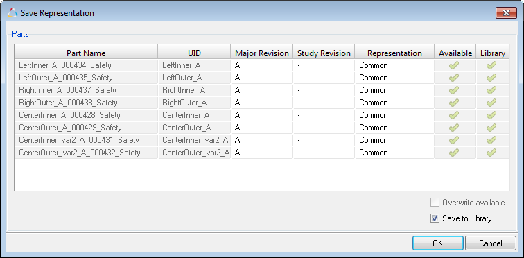
After importing a BOM and creating respective representations, you can save the representations locally or in the Part Library.
| 1. | In the Part browser, right-click on part assemblies or parts and select Representations > Save from the context menu. The Save Representation dialog opens. |
A checkmark in the Available column indicates that the representation already exists in the repository. A checkmark in the Library column indicates that a revision is already available in the Part Library.
| 2. | Edit the Major Revision and Study Revision columns to reflect the intended revisions. |
| 3. | To overwrite representations that already exist in the repository or Part Library, select Overwrite available. |
| Note: | Original CAD representations will not be overwritten because the original file location is stored as a link on the part. Enabling Overwrite available saves a Engineering Solutions binary file of the modified CAD representation in the repository. |
| 4. | To only save parts locally, clear the Save to Library checkbox. |
| 5. | Click OK. Unavailable parts are saved, and available parts are overwritten and saved if Overwrite available was selected. |
|
Part representations can be deleted from the current HyperMesh session and from the Part Library.
| 1. | In the Part browser, right-click on part assemblies or parts and select Representations > Delete > from Session from the context menu. |
| 2. | In the Delete Representations dialog, select representations to be deleted. |
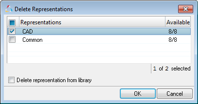
| 3. | Optional. Select the Delete representation from library checkbox to remove representations from the Part Library. |
|
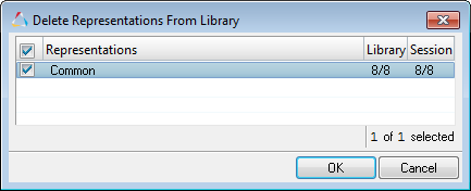
| 1. | In the Part browser, right-click on part assemblies or parts and select Representations > Delete > from Library from the context menu. |
| 2. | In the Delete Representations From Library dialog, select representations to be deleted. |
|
|
Representation entity management behavior is controlled in the Representation Load Settings dialog. Invoke this dialog by right-clicking in the Part browser and selecting Representations > Settings > Load Settings.
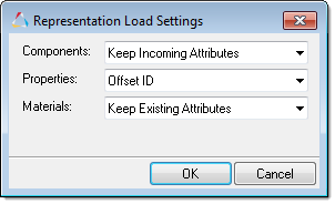
The representation entity management settings work independent of the import binary and import deck entity management settings.
The following options are available for components, properties, and materials.
| • | Offset ID. Merges incoming attributes with conflicting IDs into the session, and offsets their IDs. |
| • | Keep Existing Attributes. Maintains existing in-session entity attributes and incoming conflicting entity IDs. |
| • | Keep Incoming Attributes (default). Maps incoming entity attributes to the in-session entities. |
When Offset ID is selected for components, both incoming and existing geometry and FE residing in the component with conflicting IDs are kept. When Keeping Existing Attributes or Keep Incoming Attributes are selected for components, incoming geometry and FE that resides in the component with conflicting IDs are kept.
|
See Also:
Part Browser


