You can change the shape of a model with local domains and handles using one or more of the following methods:
| • | Moving the local handles |
| • | Changing a distance or angle |
| • | Changing the radius, curvature, or arc angle of an edge domain |
| • | Mapping nodes to a line, plane, surface, or mesh |
| • | Using section mapping, line and surface difference, and element offset |
| • | Using freehand morphing capabilities such as move nodes, record, and sculpting |
There are six ways to move handles in the move handles subpanel of the Morph panel:
|
This option allows you to move handles interactively by dragging the mouse across the screen. You select an entity such as a vector, line, plane, surface, or domains, to orient the mouse location in 3D space, and move a handle by clicking on it and dragging it to a new location. Interactive morphing is most effective for visualizing how the mesh will react when a handle is moved and for making approximate shape changes. If you want to move a handle a specific distance or to a specific position, it is better to use a non-interactive option.
|
|
This option allows you to translate handles along a vector or element normals.
|
|
This option allows you to rotate handles about an axis.
|
|
This option allows you to position handles at specific XYZ locations or place them on lines, surfaces, or another mesh.
|
| • | move to node,
move to point |
|
These options allow you to position handles at specific node or point locations, or place them on lines, surfaces, or another mesh.
|
Morphing by translating handles: By selecting the two handles along the edge of
the flange and translating them along a vector defined at the end of the section (green
and blue nodes), the length of the flange is reduced.
Morphing by translating handles: By selecting the three handles and translating them along
a vector defined at the end of the section, the width of the channel is increased.
Morphing by translating handles: By selecting the handles at the bottom of the part and translating
them upwards, the thickness of the lower section is reduced.
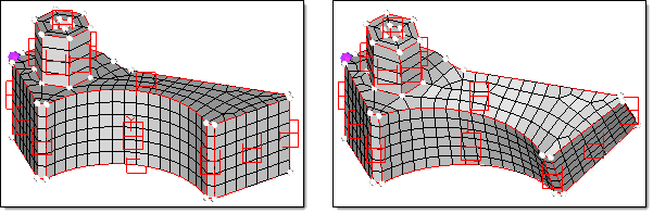
Morphing by translating handles: By selecting all the handles around the bolt boss and translating
them horizontally, the position of the bolt boss is modified.
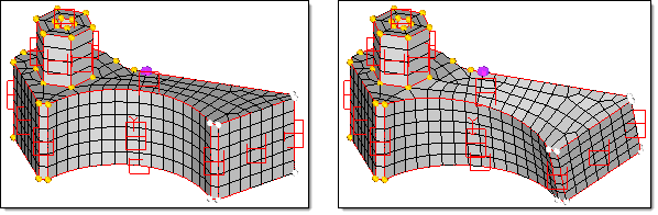
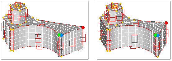
Morphing by rotating handles - constant: By selecting all the handles at the end of the section
and rotating them about a point (violet node), the end angle of the section is modified.
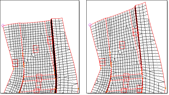
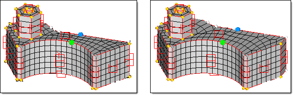
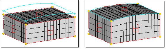
Morphing by rotating handles - constant: The right end of the block is given a constant rotation.
Morphing by rotating handles - linear: The entire block is given a linear rotation. Note how the
magnitude of the twist increases linearly with the distance from the base (purple) node.
When applying handle perturbations to your model, it is important to note that the nodes in the model follow the movements of the handles according to the influence coefficients. This concept comes into play when you are using the rotate function. After rotating handles you may find areas in the model (particularly those defined by curved edges) that are not rotated the same as the neighboring handles. This is because the nodes have followed the handles instead of being rotated about the axis. To correct this situation, check the true rotation checkbox. This will cause the nodes to be rotated as well as the handles with the amount of rotation being equal to the influence coefficient. Although it could be argued that true rotation is the "correct" way to morph via rotation of the handles, not all morphing applications are best done using true rotation.
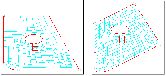
Morphing by rotating handles - normal: Although the highlighted handles are rotated, the circle
at the center of the model remains on the same plane as before.
Morphing by rotating handles - true rotation: During "true rotation" the nodes rotate
along with the handles.
While morphing a model, the following message may be displayed: "Some handles selected are dependent on others. Would you like to ignore dependencies for this operation?". This occurs when both a dependent handle and the handle on which it is dependent are selected to be morphed. If you click yes the given perturbation is applied to each handle and the dependent handles are not given an additional perturbation inherited from another handle. If you click no, the given perturbation and any inherited perturbation is applied to each dependent node. For most cases you will want to click yes.
The alter dimensions subpanel of the Morph panel allows you to change one of the parameters in the model, such as the distance between nodes, the angle between nodes, or the radius or curvature of an edge domain. The basic concept is as follows:
Select two nodes (node a and node b).
Select handles corresponding to those nodes.
The handles selected are the ones that will move to make the distance between node a and node b (or angle with a vertex selected) equal the specified value. You must select at least one handle for each end and the handle may be coincident with one of the nodes. For solid models, controlling a particular dimension often involves moving more than one handle for each end.
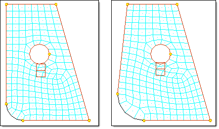
Morphing by altering dimensions - distance: By selecting the width of the bottom of the
channel as the desired distance to alter (green and blue nodes) and by selecting the handles
on the left (highlighted) to follow the green node and the handles on the right (shown as gray)
to follow the blue node, the width of the bottom of the channel can be changed from 60 to 30
with the rest of the channel changing along with it.
Morphing by altering dimensions - distance: By selecting the thickness of the block as the desired
distance to alter (green and blue nodes) and by selecting the handles on the radius (shown as gray) to
follow the green node and the handles on the back face (highlighted) to follow the blue node, the thickness
of the block between the radius and the back face is altered from 15 to 25 by moving the entire back face.
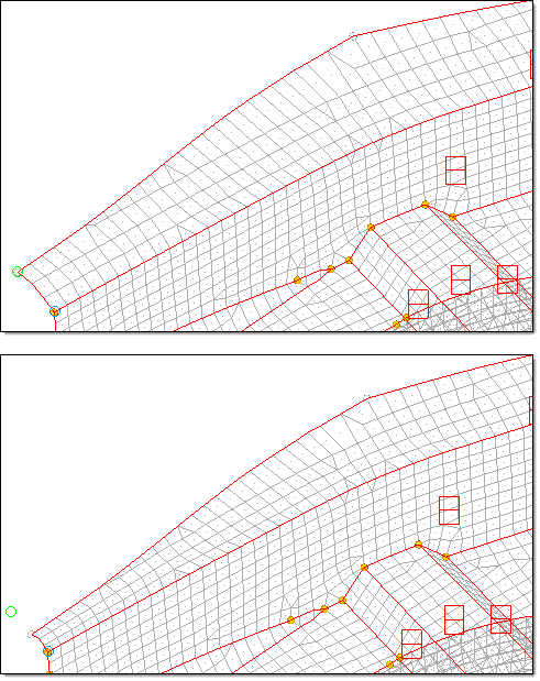
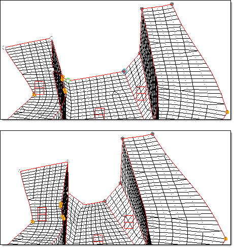
Morphing by altering dimensions - angle: By selecting the angle of the left side of
the channel (green, blue, and red nodes) and by selecting the handle at the bottom right
of the channel (shown as gray) to follow the green node and the handle at the red node
(highlighted) to follow the red node, the angle of the left side of the section is changed
from 110 degrees to 90 degrees.
Morphing by altering dimensions - angle: By selecting the angle between two faces of the
block (green, blue, and red nodes) and by selecting the handles at and directly below the green
node (shown as gray) to follow the green node and the handles at, near, and below the red node
(highlighted) to follow the red node, the angle is altered from 126 degrees to 90 degrees.
The radius, curvature, and arc angle options are used as follows. You select any number of curved edge or 2D domains, select the center calculation and style options, set the new radius, curvature multiplication, or arc angle factor for them, and click morph. All the domains are changed simultaneously.
| Note: | The curvature tool scales your radius by a factor rather than a set radius, so if you want to change a radius from 5.0 to 8.0, you need to set the curve ratio to 1.6. The curvature tool is intended for domains that do not have constant curvature. Making the bias factor retroactive does not work for radius changes. |
|
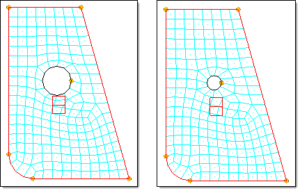
Morphing by altering dimensions – radius – center: By selecting the
edge domain around the edge of the hole, the radius is changed from 3 to 1.5.
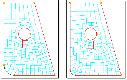
Morphing by altering dimensions - radius - fillet: By selecting the
edge domain at the corner of the part and selecting the fillet option, the
radius is changed from 5 to 2.5 and kept in line with the edges at either end.
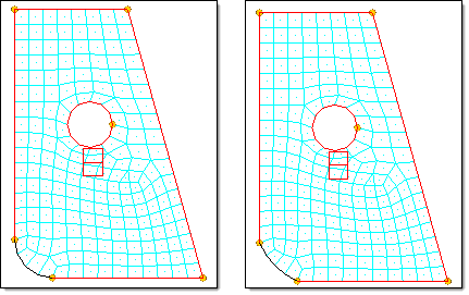
Morphing by altering dimensions - radius - hold ends: By selecting
the edge domain at the corner of the part and selecting the hold ends option,
the radius is changed from 5 to 10 with the ends held in place.
Morphing by altering dimensions - radius - hold end: By selecting the
edge domain at the corner of the part, selecting the hold end option, and
selecting a node at the end of the edge domain, the radius is changed from 5 to 8
while the held end remains in place.
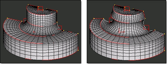
Morphing by altering dimensions - radius - fillet: By selecting all of the edge domains that
form the fillet between the flat sections and the round section and changing them simultaneously,
the fillet is reduced from 20 to 8.
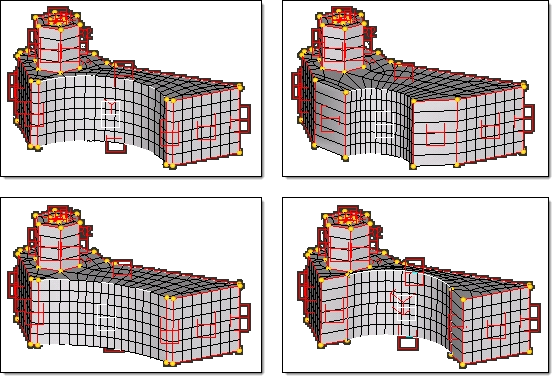
Morphing by altering dimensions - radius: The radius is changed in three different ways.
At the top right, the hold center option is used. At the lower left, the hold ends option is used.
At the lower right, the fillet option is used. In all cases, both the top and bottom edge domains
were selected as well as the 2D domain and the by normals option was used for center calculation.
This option will directly calculate the radii for the nodes on the 2D domain instead of inferring them
from the edge domains which makes this approach more accurate for 2D domains as well as more
reliable for non-uniform meshes.
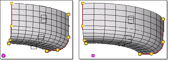
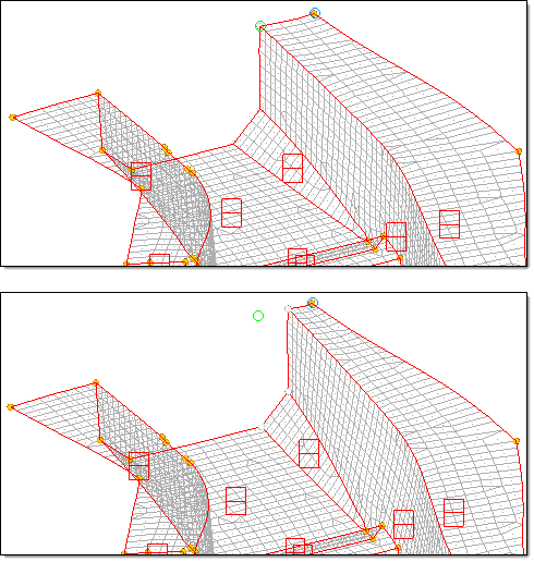
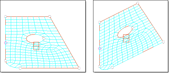
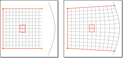
Morphing by altering dimensions - arc angle: The arc angle of the mesh is changed from 60 to 90
degrees using by axis (the vertical axis and violet base node) to calculate the center of curvature.
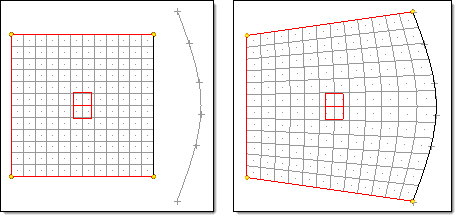
Morphing by altering dimensions - arc angle: The arc angle of the fillet is changed from 90 to 180
degrees using by normals to calculate the center of curvature.
There are five methods available for calculating the center of curvature for the selected domains:
| • | by normals - this method is the default and uses the element normals to approximate where the center of curvature is for each node in the selected domains. This method is not always accurate, but often gives good results for regular meshes. |
| • | by axis - you may select an axis which will serve as the center of curvature. |
| • | by line - you may select a line which will serve as the center of curvature. |
| • | by node - you may select a node which will serve as the center of curvature. |
| • | by edges - this method uses the edge domains to calculate the center of curvature with the center lying in the plane of the edge domains. The symmetry option refers to how the morphing of the edge domains is applied to neighboring 2D domains. The auto-symmetry option was the default for HyperMorph prior to version 8.0. In 8.0 you may choose to turn off symmetry when using this option. |
For auto-symmetry, the changes in the radii of the edge domains are applied to any 2D domain, depending on the number of edge domains you change for the 2D domains. If you change only one edge domain for a given 2D domain, the radius change will not be applied linearly across the 2D domain. If you change the radii of two edges for any given 2D domain, either a linear or planar temporary symmetry is created between the two edge domains for the 2D domain that will apply radius changes more linearly across the 2D domain. This works best if the mesh is regular. If you are changing only one edge for a 2D domain, you can increase the bias factor of any handles on an edge domain to yield a more even distribution.
Mapping an edge domain to a line or a 2D mesh to a plane, surface, or mesh is done using the Map to Geom panel. This option is very effective for fitting a mesh to new geometric data. When mapping a domain to a geometric feature, all the nodes in neighboring domains are stretched along with it, minimizing mesh distortion. You have several options for determining how the nodes for the mapped domain are placed on the geometry. When mapping an edge domain or node list the nodes can be moved normal to the line, along a vector to the line, or distributed along the full length of the line. When mapping a 2D domain or selection of nodes to a plane, surface, or mesh, the nodes can be moved normal to the target, normal to the elements of the 2D domain or selected nodes, or along a vector. If you wish to fit a mesh to a surface, there is no option to do this automatically, however, with multiple mapping operations, or using the user control option you can fit a 2D domain to a surface.
Furthermore, you have the option of creating a morph constraint between the nodes and the map target automatically after mapping. This constraint will allow you to do further morphing operations while maintaining the constrained nodes on the geometry. .
The map to geom panel is also effective for solid model meshing. You can create a block of solid elements roughly in the shape of the geometry that you are trying to mesh, and then use map to surface to morph the faces of the block to the geometry.
Morphing by mapping to line - automap - normal to geom: The edge
domain is mapped to a line by moving the nodes normal to the line.
Morphing by mapping to line - automap - fit to line: The edge domain
is mapped to the line by fitting them along the line. Any proportional spacing
between the nodes will be maintained after mapping.
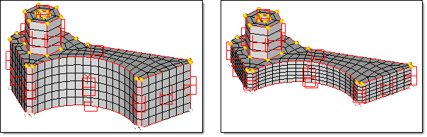
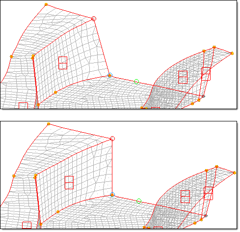
Morphing by mapping to surface: By selecting the 2D domain on the top of the solid block
to be mapped to the surface, the entire solid block is morphed to match the surface.
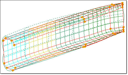
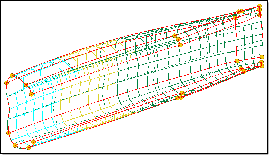
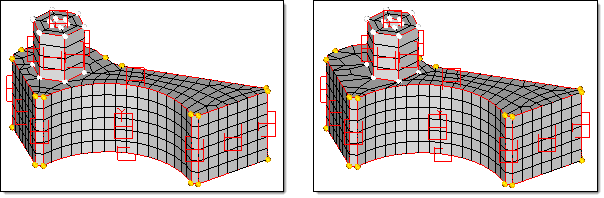
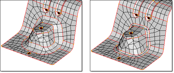
Morphing by mapping to surface: A rectangular C-section is mapped to a curved surface.
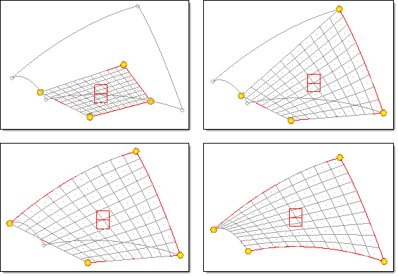
Morphing by mapping to surface - user control: This example shows the user-control approach to
mapping a mesh onto a surface. The surface and 2D domain are selected and the user control button is
clicked. This brings up a new panel which allows you to place handles or map edges prior to the surface
mapping operation. One by one each edge domain is placed on one of the lines around the target surface
using the fit to line option. This stretches the 2D domain to match the surface more closely than before.
When the map button is clicked, the domain is the mapped to the surface, fitting it perfectly to the geometry.


