Use the UG Part browser to filter and select options for importing UG parts and assemblies. The browser opens when you import an UG file from the Import tab.
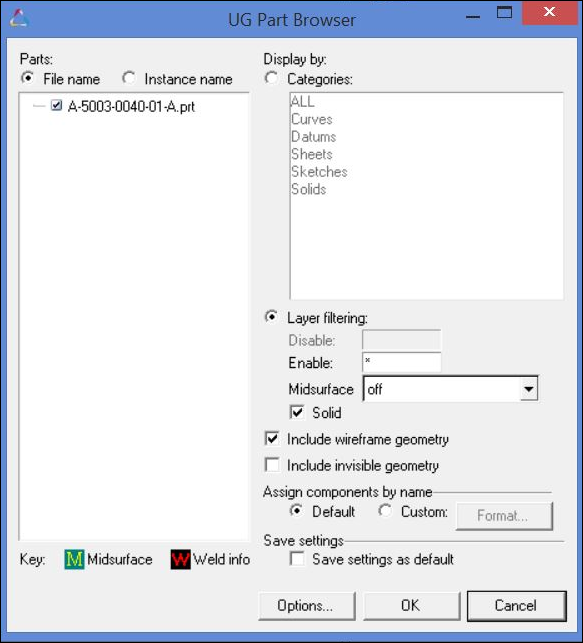
On the left of the browser is the model tree. The parts listed in the model tree are shown either using the File name or Instance name options. To select a part import, select its check box. If the root is selected, all parts are considered selected. Root assembly/part is selected by default.
The UG Part browser searches all part files for weld information as well as mid-surface definitions. Parts in the assembly that have welds assembled to them are marked with  . Parts with mid-surface definitions are marked with
  .
.
On the right of the browser are the available import options. These options include:
| • | Display by: - Determines whether to import the selected Categories for the parts specified in the model tree, or whether to use Layer filtering to import only selected layers for the parts specified in the model tree. |
| - | When the Categories option is enabled, some categories may be available in multiple parts/assemblies and some may be available in only one. You can choose multiple categories to import. All the categories for the selected parts are imported. |
| - | When the Layer filtering option is enabled, you can specify specific layers to Enable or Disable for import. To designate more than one layer or a range of layers, use commas and dashes. For example, 1,4-7 designates layers 1, 4, 5, 6 and 7. An asterisk (*) matches everything. Only one of these two options may be specified. If any layers are specified for Disable, all other layers containing entities are imported. The default is to enable all layers. |
| - | When the Layer filtering option is enabled, you can additionally choose to import the Midsurface geometry and/or the Solid geometry. |
| - | There are three options for Midsurface import. Off (default) does not import any midsurface geometry, on imports only the midsurface geometry that is visible, and always imports all midsurface geometry regardless of visibility. |
| • | Include wireframe geometry: Determines whether to import free curves and points. The default is to import these entities. |
| • | Include invisible geometry: Determines whether to import geometry contained in invisible layers. The default is to not import these entities. |
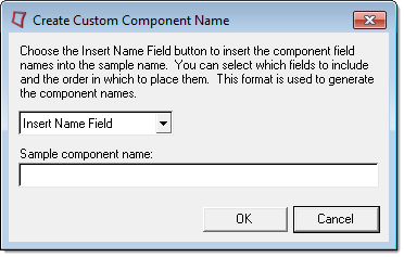
| • | Assign components by name: Customizes the organization and names of components (UG parts). The naming options are specified using the Format button as described below: |
<Part Name>
|
Uses the string attribute DB_PART_NAME from the part. If that attribute does not exist, the part file name is used.
|
<Part Number>
|
Uses the string attribute DB_PART_NUMBER or DB_PART_NO from the part. If that attribute does not exist, the part filename is used.
|
<Category>
|
Creates and names components based off of the NX categories associated with the geometry.
|
<RID-PDI>
|
Uses the string attribute DB_PART_REV from the part.
|
<Layer>
|
Creates and names components based off of the layers of the geometry being imported.
|
<Instance Name>
|
Uses the name of the part's instance in an assembly. If the part is the root of an assembly, the part filename is used.
|
<Material Name>
|
If a material is specified for the geometry being imported, the name of the material is used. Otherwise, the name of the component is unaltered.
|
<Thickness>
|
If the geometry being imported is a midsurface with thickness information, the thickness value is used. Otherwise, the name of the component is unaltered.
|
<UG Body ID>
|
The internal numerical ID of each geometric body. This value is unique for each geometric body imported.
|
<UG Tag>
|
The internal numerical tag of the part instance. This value is unique for each part instance imported.
|
| • | Save settings as default: Saves the settings into a customized ug.ini file in the current working directory for future use. |
| • | Additional options for coordinate system, weld creation, merging assemblies, and importing of attributes can be accessed by clicking Options at the bottom of the browser. These options include: |
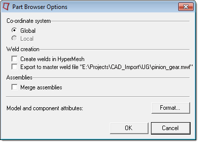
| - | Co-ordinate system: Determines whether to import an individual part from an assembly in the global coordinate system or its local coordinate system. If the whole assembly file is selected, it can only be imported in the global coordinate system. |
| - | Create welds in HyperMesh: Provides for the use of two methods to create welds. They are placed in a component named ^weld. |
| ▪ | If the part file has mid-surface definition and the Midsurface option is selected while reading the part, the welds are created between two mid-surfaces. |
| ▪ | If there is no mid-surface definition or the Midsurface option is not selected while importing the part, the welds are created as they were initially created in the UG part file. |
| - | Export to master weld file: Writes a master weld file from the weld data that can later be used to create the welds. |
| - | Merge Assemblies: If some parts of an assembly have been previously loaded and you want to add additional parts from the same assembly, you can choose to merge the parts with the existing assembly using this option. |
| - | Model and component attributes: Select the attributes in the UG part file that are to be imported. Currently, the UG readers have the ability to import any user-defined attributes attached to a UG part, and attach that information as metadata to the component corresponding to the UG part. The naming options are specified using the Format button. |
The values setup and used to populate the UG Part browser are stored in a file named ughm16.txt, located in the current working directory.
See Also:
UG Import Options


