|
»Click here to display Table of Contents«
|

User Defined Features |

|

|

|

|
|
User Defined Features |
|
|
|

|
|
»Click here to display Table of Contents«
|
User Defined Features |
|
|
|
|
|
User Defined Features |
|
|
|
|
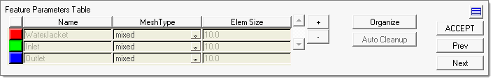
This step helps you locate and organize miscellaneous features such as water jackets, inlets, outlets, contact surfaces, and so on. These features are listed in a table on the panel, so you can add or remove components by clicking the appropriate buttons. As with other tables in the Process Manager, each entry is color coded and you can select specific table entries by clicking on the colored box at the beginning of its row.
The following buttons are available in the Tetramesh Process Manager:
Buttons |
Description |
||
+ (button) |
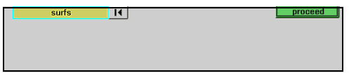
In order to create a feature, you must create a component to represent it and then add the relevant model surfaces to the component. Clicking + opens a prompt, from which you can create the new component. You can then add surfaces to that component, using the surfs collector that displays in the panel area.
As you click surfaces in the graphics window, Engineering Solutions automatically adds surfaces "by face" to the selection, so all of the surfaces associated with the same face in the model are added en masse. Click the proceed button in the panel area once you have collected some surfaces associated with the feature. This opens the Organize panel, where you can verify the surface selection and add or remove surfaces from the component. Clicking return in the Organize panel returns to the process manager's User Defined Feature Parameters Table. The features are now sorted into color-coded components and the corresponding table rows are colored to match as shown above. |
||
Auto Cleanup |
Click a table row to make it active, then click this button to open the Autocleanup panel. There, you can perform automated geometry cleanup operations on the geometry contained in the selected component. The Autocleanup panel performs cleanup operations based on the criteria set in the BatchMesher criteria file. Cleanup operations include equivalencing free edges, fixing of small surfaces (relative to the element size), and detection of features such as beads. It also performs specified surface editing/defeaturing operations like removal of pinholes below a specified size, removal of edge fillets, and the addition of a layer of washer elements around holes. The Autocleanup panel performs the entire geometry cleanup portion of the BatchMesher. Since it performs a variety of geometry cleanup tasks, the results will not be instantaneous and can take a few minutes for large models. Cleanup criteria is determined by the BatchMesher parameter and element quality criteria files, both of which can be edited from within this panel using the BatchMesher Parameter Editor. |
||
- (button) |
This button removes the currently active row from the table, deleting the corresponding component. Engineering Solutions returns all related surfaces to their original components.
|
You can back up to the Mesh Holes panel by clicking Prev. When finished cleaning up fillets click either ACCEPT or Next to continue. You can also click on a specific task in the Process Manager to go to the appropriate panel.