|
»Click here to display Table of Contents«
|

Autopitch Tool |

|

|

|

|
|
Autopitch Tool |
|
|
|

|
|
»Click here to display Table of Contents«
|
Autopitch Tool |
|
|
|
|
|
Autopitch Tool |
|
|
|
|
The Autopitch functionality is accessible via the Connectors > Create > Autopitch pull-down menu.
During the model build process it is often the case that the weld data from CAD is unavailable. The weld data is typically published days, weeks or even months after the CAD part data is published. Once the CAD part data is handed over to the CAE group the model build can begin, however, without the weld data, some assumptions are required. The Autopitch tool is designed to create weld points at a predefined pitch distance so that the model build process can continue without the need to wait for the published weld data from CAD.
The input to the Autopitch tool is components – if there is no current component collector then a new collector called ^autopitch is created.
The output from Autopitch is a series of connectors with the appropriate pitch distance and other associated parameters. These connectors are in the unrealized state, thereby allowing the connector to be realized to a configured state via the Spot connector panel.
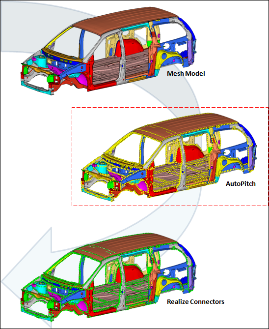
Starting with a CAD model, Autopitch creates unrealized connectors (yellow) which are then realized via the Spot panel.
| 1. | Using the Components selector, select the components you wish to automatically add connectors to. |
All selected components will receive connectors with the same qualities, so you can perform a blanket application of connectors--using the same pitch--to all components that need them as a single operation. Be wary of simply selecting the whole model, however, as this could result in undesirable actions, such as adding welds to a cars tires.
| 2. | Optional. Select Consider closed shell thin solids to additionally use shell meshes that enclose a volume (some small gaps are allowed) as input. |
For example, the outer skin of a solid part can be shell meshed and used as input to create connectors. Standard mid-plane meshes are also still considered when this option is used.
| 3. | Optional. Select Create in middle to create connectors in the middle of the found flanges. When this checkbox is disabled, connectors are created on either one of the flanges. This applies to both mid-plane and closed shell thin solid inputs, when appropriate. |
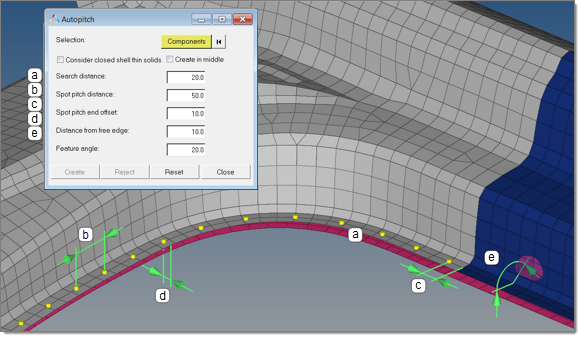
| 4. | Define the following inputs to |
| a) | Search distance. Distance to consider between components. |
| b) | Spot pitch distance. Distance between each connector. |
| c) | Spot pitch end offset. Distance from the end of an edge or flange to the connector. |
| d) | Distance from free edge. Distance from the free edge to the connector. |
| e) | Feature angle. The feature angle is used to segregate the model into faces that are planar within its specified value. |
This segregation is used to identify where autopitch connectors are placed. For example, faces found to have significant topological complexity are not used to create autopitch connectors.
| Note: | By reducing its value, the complexity of some of these faces is generally reduced. Of course, flat regions are unaffected by the parameter. |