|
»Click here to display Table of Contents«
|

FEMSITE Utility |

|

|

|

|
|
FEMSITE Utility |
|
|

|

|
|
»Click here to display Table of Contents«
|
FEMSITE Utility |
|
|
|
|
|
FEMSITE Utility |
|
|
|
|
The FEMSITE tool is a third party tool that is used to create specialized connector realization types which can be used in fatigue calculations. In HyperMesh, use the FEMSITE utility to preprocess models and submit connection information to the FEMSITE generator.
The FEMSITE utility is only available in the Nastran user profile for Windows and Linux platforms. The FEMSITE menu options will only appear if an installation of FEMSITE is found on your computer. Add the hmfemsite.ini initialization file to one of the following four locations:
The Nastran user profile searches all four locations for the hmfemsite.ini file in the order listed above, and uses the last found existing file to parse the variables pointing to your FEMSITE installation.
Example: hmfemsite.ini File Contents
Lines that do not contain the strings FEMSITE_DATA_DIR=, FEMSITE_LINUX_DATA_DIR=, FEMSITE_EXE=, or FEMSITE_LINUX_EXE= will be ignored, and can be treated as a comment. If Hypermesh does not locate the FEMSITE exe or the data directory, the FEMSITE menu options will not load. Welds need to have a minimum amount of metadata in order to be realized within FEMSITE. The Define Spotweld, Define Robscan, and Define Rivet options in the FEMSITE utility allow the assignment of this metadata from within Hypermesh (instead of via CONN file) for spotwelds, Robscans and Rivets.
|
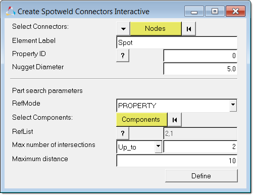
From the menu bar, click Connectors > FEMSITE > Define Spotweld. In the Create Spotweld Connectors Interactive dialog, define the spotweld. Defining a spotweld with the FEMSITE utility ensures that you will be able to create a FEMSITE spotweld within Hypermesh, and assign the proper metadata to the connector for successful realization. You can create a new connector with nodes, or change existing connectors to FEMSITE connectors. The Element Label is used in FEMSITE. The Property ID and Nugget Diameter are sent to the FEMSITE executable. The RefMode (reference mode) for connector assignment can be by Property ID or Part ID. The assigned IDs are found once components are selected, and listed in the RefList. The Maximum number of intersections field defines the maximum number of connector links to create, and the Maximum distance field defines the search tolerance the FEMSITE executable should use for realization.
|
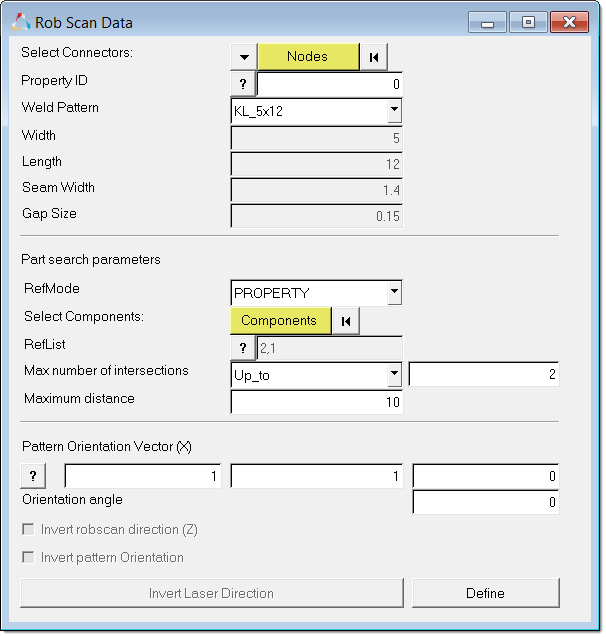
From the menu bar, click Connectors > FEMSITE > Define Robscan. In the Rob Scan Data dialog, define the Robscan weld. Create multiple Robscan weld patterns by selecting node location input or selecting an exiting connector (for example a connector imported from a connector file). The values in the Width, Length, Seam Width, and Gap Size fields are populated after a Weld Pattern has been selected. The Property ID is sent to the FEMSITE executable. The RefMode (reference mode) for connector assignment can be by Property ID or Part ID. The assigned IDs are found once components are selected, and listed in the RefList. The Maximum number of intersections field defines the maximum number of connector links to create, and the Maximum distance field defines the search tolerance the FEMSITE executable should use for realization. The orientation of the weld is defined with a triad (x,y,z) and orientation angle. Preview the orientation of the weld by clicking “?”. You can also reverse both direction inputs by enabling the Invert Robscan direction (Z) checkbox.
|
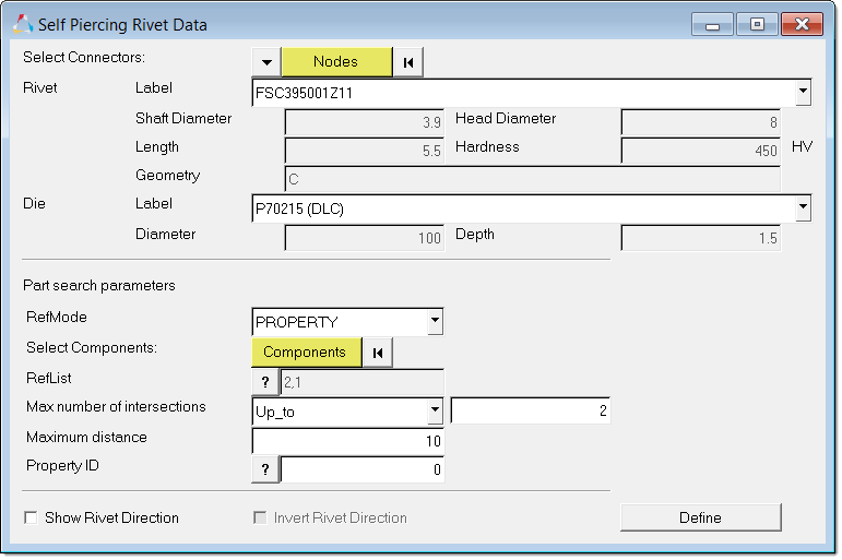
From the menu bar, click Connectors > FEMSITE > Define Rivet. In the Self Piercing Rivet Data dialog, you can create multiple Rivet configurations. The values in the Shaft Diameter, Head Diameter, Length, Hardness, and Geometry fields are dependent on the Label selected. Diameter and Depth are dependent on the Die Label selected. The RefMode (reference mode) for connector assignment can be by Property ID or Part ID. The assigned IDs are found once components are selected, and listed in the RefList. The Maximum number of intersections field defines the maximum number of connector links to create, and the Maximum distance field defines the search tolerance the FEMSITE executable should use for realization. The rivet direction is defined by the normal of the shells. Reverse the default direction input by enabling the Invert Rivet Direction checkbox.
|
A FE model does not need to be imported into HyperMesh prior to importing a *.conn file.
Required *.conn File Format & GuidelinesIn order for *.conn files to be successfully imported, they must be properly formatted, and connectors and metadata must be properly defined.
If *.conn files are missing important parameters, the following attributes are set:
The internal HyperMesh parameter ce_diameter is synchronized with TAN_DIM1 during import. This parameter is used for realization in HyperMesh (diameter).
|
PART/PID mapping files are *.csv files generated by the BOM tool. This function is used with tailored blanks, where one part consists of several property IDs. REFMODE is set to PROPERTY when referencing two properties, or it is set to PART when referencing parts. For every PID, there is a corresponding component which is used to reference a connector. For every PART, there is a corresponding assembly which is used to reference a connector. The mapping of components/assemblies (PID/PART) can be done using an external file. The external file specifies the assembly structure in HyperMesh.
|
Connector data that has been imported or defined in HyperMesh can be exported to *.conn files.
|
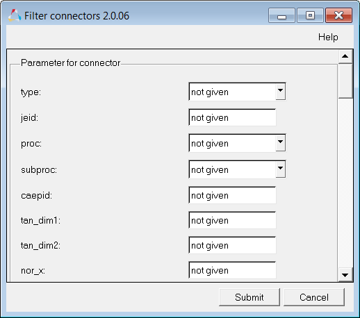
Use the FEMSITE Filter tool to filter connectors in the graphics area based on metadata.
|
From the menu bar, click Connectors > FEMSITE > Check Connected to check if the connection partners of connectors are available in the HyperMesh database. After a check is performed, the number of connectors that have no existing connector partners in the HyperMesh database is reported, and failed connectors are displayed. There is no geometrical check done if a projection is possible, only the availability is checked. When REFMODE is set to Part, only assemblies are checked. PIDS are not checked.
|
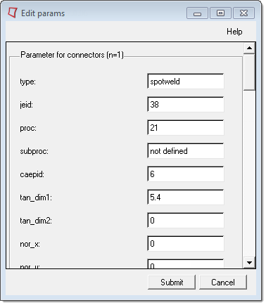
All of the supported connector metadata that can be imported is listed in the parameter.cfg file, which can be found in the installation: /config/parameter.cfg. If certain metadata is not applicable to you, create comments for them using "#". HyperMesh will ignore metadata commented with "#". Use the FEMSITE Review CONN tool to review and edit connector metadata that was created during import.
|
If you are working in a HyperMesh model that contains existing connectors that were imported from a *.conn file, they will appear in the Connector browser as undefined custom types. In order for these connectors to appear with the correct connector type, they must be assigned metadata. From the menu bar, click Connectors > FEMSITE > Assign Metadata to assign metadata.
|
See Also: