| • | The skin offset method is recommended whenever constant thickness parts without ribs/t-connections require mid-surface generation. This method is the fastest and most efficient for such models. |
|
Surface Hole Recognition
| • | For improved mesh flow, an even number of elements should be specified. Usually, this value is set to comply with the min and max element size requirements. While not recommended, it is permissible to set this so that the element size violates the min or max element size restrictions. The use of the auto setting is not recommended for holes with washers. |
| o | The following formula can be used to calculate the resulting element size S given a hole radius R and number of elements around the hole N: |
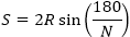
For example, a hole with a 2.5 mm radius and 6 elements around the hole will result in a mesh size of 2.5 mm.
| o | To not have elements smaller than the min element size around holes, use a radius threshold for removal > = 0.708*min element size. |
| • | Incompatible settings for holes with washers can lead to the creation of failed elements and/or outer washer ring elements with lengths significantly different from the target mesh size. This can lead to bad mesh flow and bad transitions to the regular mesh. |
| o | It is not recommended to set the number of elements for a hole with washers to less than 6. |
| o | Using minimal mode for # elems and auto mode for washers is recommended whenever possible, as it gives the most flexibility. With these settings, the outer washer element size is close to the target element size, and the washer elements comply with the quality criteria. However, washers will not be built if it is not possible to create elements of permissible quality, or the outer washer ring element size appears significantly larger than the target element size. Another side effect is that as a last resort, a washer may be built with an odd number of elements in order to build a good quality washer. |
| o | When specifying an exact number of elements for holes and/or a fixed number of elements (or radius fraction) for washers, consider the implication to the element quality (aspect ratio, min/max size, Jacobian) and the outer washer ring element size, using the formula as above. |
| o | It is possible to create washers with failed elements and/or with an outer washer element size different from the target element size. This is done by defining washers as a fixed number or as a radius fraction. Use exact mode for # elems if it is expected that the outer ring element size is more than 140% or less than 60% of the target element size. In addition, when a hole is set to high priority, washer elements are not modified to correct for failed element quality. If a hole is set to normal priority, washer nodes are allowed to move to correct the quality. |
| • | Use the Attempt to maintain narrow slots rounded ends using >= 6 elements option only if absolutely necessary. Meshing of small areas produced by this option will often have a negative impact on the mesh flow. |
Solid Hole Recognition
| • | This should be disabled for models having only shell geometry, as the recognition of the solid holes is potentially time consuming. |
| • | Define even numbers of elements around holes, trying to comply with the min element size criterion and trying to have the element size as close to the target element size as possible. |
Surface Fillet Recognition
| • | The following formulas define how the fillet geometry parameters and the mesh density are related: |

W – fillet arc width, R – fillet radius,  – fillet arc angle (radians), Wch – fillet chordal width, S – element size across the fillet, N – element density across the fillet, D – chordal deviation; – fillet arc angle (radians), Wch – fillet chordal width, S – element size across the fillet, N – element density across the fillet, D – chordal deviation;
| • | Enabling the Minimize transitions option is highly recommended. However, in very rare occasions it may create rows of strongly skewed elements. This may happen for fillets having multiple irregular fixed points on the fillet sides, or multiple intersections of those edges. For such cases, it may be disabled to improve the result. |
Flange Recognition
| • | It is recommended to use a minimum of two elements across the flange width. The actual number of elements is determined internally by accounting for restrictions on the min and max element sizes, as well as the aspect ratio. |
| • | A reasonable upper limit for the maximum flange width is around (N + 1.5) * element size, where N is the number of elements across the flange. Similarly, a reasonable lower limit is two times the min element size. |
Other Options
| • | The threshold for the Suppress narrow fillets and surfaces with width < option may be increased if the rate at which tria elements or elements with a small size are reduced should be more aggressive. This may be important when the min element size is less than 10%-20% of target element size. The threshold may be reduced if some important fillet edges are being suppressed. |
| o | The Recognize main fillet strips and preserve main edges options have minimal effect when Recognize and preserve major feature edges is enabled. |
| • | The Suppress beads with height < value is dependent on specific modeling requirements. Typically, this is set around 20% of the target element size, but not larger than the criteria minimal element size. |
| • | The Suppress flanged holes with height < option is usually set to 20% of the target element size, and not more than 70%-80% of the min element size. |
| • | The Remove edge fillet with radius < recommended upper limit is between the min element size and the target element size. |
| • | For logo removal, a Concavity factor value of 2.0 is recommended for logos with complex lettering. For logos with simple shapes, though, a value of 1.0 or even 0.0 may be used. In this case, to reduce the danger of removing valid features, assign height < a value no greater than the Suppress beads with height < value. |
|
| • | Recognize and preserve major feature edges aims to strongly preserve major detected features, though element quality may be decreased. However, the rate of elements with bad quality is not high, and therefore this option is generally recommended. |
| o | This may be disabled in order to reduce the number of elements failing the quality criteria, if the modeling guidelines do not have strong feature capture requirements. Even in this case, features are still captured in a less strict sense. |
| o | It is not recommended to use midline split for treating surface fillets when this option is enabled. Currently, the created midline is not considered as a major feature edge and may not be preserved. Another possible side effect of midline split includes possible poor geometry patterns for partial fillet recognition. |
| • | It is highly recommended to enable the Recognize and suppress construction edges option, which suppresses unimportant construction edges on faces of small curvature and extra fillet transversal lines. It significantly helps to improve the mesh flow and reduce the number of tria elements. |
|
| • | For most applications, it is recommended to use the mixed type for Create mesh with element type. Note that when the quad type is set, a specific algorithm is used which may have negative effects on the mesh flow and may create undesirable mesh patterns (for example, three quads sharing a node). |
| o | Enabling both the align and size mesh flow options is highly recommended, as they have minimal negative side effects. |
| • | Enable improved fillet mesh flow is currently an early development and it is therefore not enabled by default. However, it may make sense to enable this if the standard fillet mesh is not acceptable. |
| • | Apply tria reduction with min elem size > enables a very effective and powerful cleanup step that not only may significantly reduce the number of tria elements, but also improves mesh flow. It is therefore highly recommended. |
| o | If the rate of small elements generated on large surfaces increases with this enabled, increase the min elem size > parameter to a value greater than 50% of the target element size. |
| o | The tria reduction tool is enabled only if across edges is set as the Apply optimized smoothing method. This restriction is unnecessary and will be removed in a future release. |
| • | As a standard behavior, BatchMesher introduces trias around holes only when it is necessary to meet the quality requirements. Therefore, enabling Remove trias attached to holes may lead to a deteriorated mesh quality. |
| • | From the point of view of post-mesh element cleanup, edges are classified in the following way: |
| o | Strong feature edges – non-manifold edges, user preserved edges and edges identified as major feature edges in the geometry cleanup steps. |
| o | Feature edges – edges that have strong surface curvature breaks, or that have a large angle between the elements sharing the edge (as defined by the Feature angle during elements cleanup value). |
| o | Non-feature edges – edges having very small surface curvature breaks, or that have a small angle between elements sharing the edge (as defined by the Feature angle during elements cleanup value). |
| • | The method chosen for Apply optimized smoothing effects the capabilities of all post-mesh element cleanup operations. The across edges mode is set by default and is strongly recommended, as it allows for the most flexibility in correcting the mesh. Other options are likely to result in a high rate of failed elements because: |
| o | Geometry cleanup and defeaturing cannot address all problems. |
| o | Many important geometry features are conflicting. For instance, a bead may be near to a major fillet edge. While this may be difficult to resolve at the geometry level, it can be easily corrected at the element level. |
The across edges mode attempts cleanup steps in the following order:
| o | Move nodes only along surface edges. |
| o | Move nodes only across non-feature edges. |
| o | If the Apply failed features cleanup option is enabled, which is highly recommended, the following is attempted: |
| ▪ | Only strong feature edges are preserved, except that very narrow elements between strong features are allowed to collapse. |
| ▪ | Nodes are allowed to move off of the non-major feature edges. This fixes most of the failed elements. However, some geometry features could be dissolved as a result of local cleanup. To help avoid this, it is also recommended to enable the try to keep the shape of features option. With this enabled, small nodal movements are enabled instead, which help to preserve the features shape. Sometimes this option may have a reverse effect, where some narrow elements are extended instead of collapsed. |
Other methods are likely to result in a high rate of failed elements because:
| o | Geometry cleanup and defeaturing cannot address all problems. |
| o | Many important geometry features are conflicting. For instance, a bead may be near a major fillet edge. While this may be difficult to resolve at the geometry level, it can be easily corrected at the element level. |
| • | Remaining failed elements are fixed using small constrained node movements for feature edges, including strong feature edges. The only exception is that user preserved edges are excluded from such movement. The Correct features parameters provide control over these movements. |
| o | For Move nodes across shared edges, max dist <, the suggested value is 10% of the target element size. |
| o | For Move nodes across free edges, max dist <, the suggested value is 5% of the target element size. |
| • | For correcting warpage of quad elements, it is recommended to enable the Offset nodes from surfs, max dist <, and Divide quads into trias options. |
| o | The recommended value for the offset distance is10% of the target element size. |
| o | When both options are enabled, warped elements are first fixed by nodal movements normal to the geometry, followed by splitting any remaining failed quads. |
| • | The recommended value for Feature angle during elements cleanup is 20o-30o. A lower value may help with better feature representation, but a value lower than 15o may significantly increase the rate of failed elements. |
|
|


