The Geometry Cleanup section defines a variety of geometry feature recognition and preparation tasks performed by BatchMesher. There are a number of default defeaturing tools, which operate mainly based on the min element size defined in the criteria file. These tools merge small/narrow surfaces, remove narrow faces/tails, etc… They are not directly controllable by the user, outside of properly defining the min element size.
The main tools for defeaturing include suppression of geometry edges and vertices to merge narrow and small surfaces and edges, and splitting surfaces to guide the mesh flow.
A final set of tools are based on the recognition of classified features like beads, dimples, flat bottom bosses/depressions, flanges, fillets, holes/tubes, etc… These features are simplified “intelligently”, allowing the preservation of the main feature edges, while still merging/splitting internally as required.
There is a tradeoff between mesh quality and feature capture. Over-simplification of geometry results in dissolving of important features, and often in bad mesh flow. Under-simplification results in decreased element quality, increased numbers of trias, and bad mesh flow. So it is important to define all of the settings appropriately.
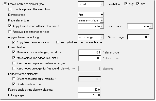
When Geometry Cleanup is activated, the following cleanup parameters, that can be turned on and off independently, become enabled:
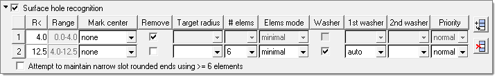
When Surface hole recognition is activated, surface holes of different sizes are recognized and treated appropriately. A table becomes enabled to define the radii ranges and additional options:
Option
|
Action
|
Add Line ( ) )
|
Adds an empty row to the end of the table.
|
Delete Line ( ) )
|
Removes the selected row from the table.
|
R<
|
The maximum radius of the current hole range. The minimum value is taken as 0.0 for the first row, or as the maximum value from the previous row. For slotted holes, the radius is measured at the tip of the hole.
|
Range
|
The radius range for the current row. This value is read-only.
|
Mark center
|
Option to create a node and tag at the center of the hole, or to do nothing.
|
Remove
|
Remove (defeature) the hole. For slotted holes, the hole is removed only if the tip radius is less than the specified radius threshold, and the length of the hole is less than 1.4 times the target element size.
If Remove is disabled, the following options are available:
| • | Target radius adjusts holes in the range to have the specified target radius. The radius can be specified as an exact value (for example 5.0), or as an expression based on the original radius (for example radius*1.1, radius-0.5, radius+0.5). |
| • | # elems specifies the minimum/exact number of elements to create around the holes. If set to auto, the number of elements is internally selected so that the min and max element size requirements are satisfied, with the best possible representation of the hole shape. Auto is not recommended for holes with washer layers. |
| • | Elems mode determines whether # elems defines the minimum or exact number of elements. |
| • | Washer creates washer layers around holes. If specified, one or two layers can be created. |
| | 1st washer sets the width of the first washer as a constant value (select the blank entry in the drop down and enter a value), a scale of the hole radius (for example 0.6*radius), or an automatic determination based on element quality. |
| | 2nd washer sets the width of the second washer as a constant value (select the blank entry in the drop down and enter a value), a scale of the hole radius (for example 0.6*radius), or an automatic determination based on element quality. If the value is left blank, no washer will be used. |
| | Priority sets the priority of one radii range over the others. For example, if you wish to ensure all bolt holes (radii 10-15) have correct washers but other holes are not critical, holes with radii 10-15 will receive higher priority than others. This ensures that if two holes close to each other in the model have overlapping/conflicting washers, the hole with higher priority gets the washer while the other does not, or the hole with the lower priority may get a modified washer instead. In addition, when a hole is set to high priority, washer elements are not modified to correct for failed element quality. If a hole is set to normal priority, washer nodes are allowed to move to correct the quality. |
|
Attempt to maintain narrow slot rounded ends using >=6 elements
|
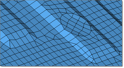
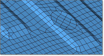
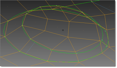
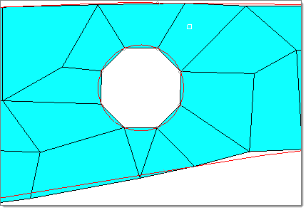
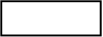
Select this check box to attempt to generate a mesh using the pattern indicated in the image below.
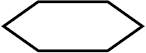
Clear this check box to attempt to generate a mesh using the pattern indicated in the image below. In the pattern below, there are six elements, two on each long side and one on each end.
|
|
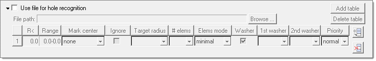
When Use file for hole recognition is activated, you provide a file containing X, Y, Z center locations of all of the holes to consider. This is useful for special treatment of specific holes, usually bolt holes.
BatchMesher compares the defined locations to the holes in the model, and prioritizes the holes that match. All of the options for Surface hole recognition are available for these holes. If one or more holes files are defined, BatchMesher looks for the found holes in each file, in the order the files are defined. If found, it applies the washer table linked to the first found file to the corresponding holes. If a hole is not found in any file, the settings from the default general surface holes table are used.
Multiple files can be specified, each with their own definitions. The order of the files determines the order of precedence in the case where there are overlapping or conflicting definitions.
| • | Add table adds a new table for creating a new hole file. |
| • | Delete table deletes the specified hole file table. |
The holes file must contain one line for each hole, with the values either space, tab or comma separated. Each line contains a line number followed by the X, Y, Z locations of each hole center. For example, using spaces/tabs with line numbers:
1 1420 -839 65
2 1724 -846 212
3 1683 -845 265
4 1660 -841 308
Or using commas with line numbers:
1,1420,-839,65
2,1724,-846,212
3,1683,-845,265
4,1660,-841,308
|
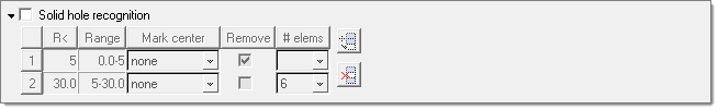
When Solid hole recognition is activated, solid holes (cylindrical surfaces in volumes) of different sizes are recognized and treated appropriately. A table becomes enabled to define the radii ranges and additional options:
Option
|
Action
|
Add Line ()
|
Adds an empty row to the end of the table.
|
Delete Line ()
|
Removes the selected row from the table.
|
R<
|
Specifies the maximum radius of the current hole range. The minimum value is taken as 0.0 for the first row, or as the maximum value from the previous row.
|
Range
|
The radius range for the current row. This value is read-only.
|
Mark center
|
Select whether to creates a node and tag at the center of the hole, or to do nothing.
|
Remove
|
Removes (defeature) the hole. If Remove is disabled, you must specified the minimum/exact # elems to create around the holes.
|
|
Recognizes surface fillets in order to perform one or more of the following options:
| • | Prevent the main (long) edges of the fillets from being suppressed, and also prevent the nodes of those edges from moving while fixing element quality. |
| • | Remove/defeature fillets. Gaps may result if complicated fillets cannot be removed. |
| • | Split the fillets along the mid-line and suppress the edges. |
| • | Specify the number of elements across the width of the fillets for given fillet radii. |
| • | Specify the chordal deviation to be achieved while meshing. |
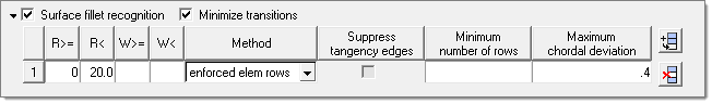
In the surface fillet recognition table, you can define a desired number of element rows for specific ranges of average fillet radii, width, or both. The width value is defined is the arc length of the fillet.
In the following image, uniform fillet strips with an average radius between 3 and 5 and an average width between 2.0 to 9.0 will be meshed with one row of elements; uniform fillet strips with an average radius between 5 and 20 and an average width between 9.0 to 16.0 will be meshed with two rows of elements; and uniform fillets strips with an average radius between 20 and 30 and an avarage width between 16.0 to 24.0 will be meshed with three rows of elements. This rule does not apply to fillets with an average element width below or above the defined ranges of non-uniform fillet strips (when minimal and maximal width of fillets exceed 30%).
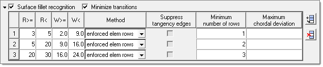
If the width or number of rows columns in the surface fillet recognition table are empty, the next default value will be applied. In this example, that means uniform fillet strips with an average fillet width between the element sizes of 0 to 2.0 will be meshed with one row of elements.
A fillet can be meshed with enforced rows of elements, or split at its midline and meshed accordingly based on element quality.
The mesh settings can be defined as an exact number of rows when Minimize transitions is disabled. This allows the Suppress tangency edges option to also become available. When enabled, fillets are treated by making a midline and suppressing the fillet itself. This combination may be selected to defeature very narrow fillets. Midline spliting without suppressing tangency edges can be used for wide fillets to ensure that the fillet mesh will be symmetrical.
Enabling Minimize transitions helps to reduce trias. The mesh settings are then provided either as a minimum number of elements and/or determined based on a maximum chordal deviation criterion. BatchMesher calculates the required number of elements as the maximum of the user-specified number of rows and the number of elements required to meet the maximal chordal deviation.
Note that the minimal element size and aspect ratio criteria requirements are always honored. This means that the element quality restrictions have the highest priority when calculating the element density for a fillet range.
|
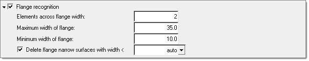
When Flange recognition is activated, geometry that represents flanges on sheet metal parts is recognized and the below options become enabled. Flanges may be modified to suppress construction lines, subdivide them into rectangular areas, or otherwise prepare them for proper meshing. As this functionality is not supported for solid geometries, it should be disabled for such models to improve performance.
Option
|
Action
|
Elements across flange width
|
Specifies a minimum number of elements to be created across the flange width.
|
Maximum width of flange
|
Specifies a maximum flange width to consider for flange recognition.
|
Minimum width of flange
|
Specifies a minimum flange width to consider for flange recognition.
|
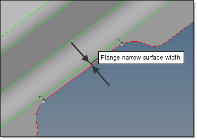
Delete flange narrow surfaces with width <
|
Controls the removal of narrow flange surfaces to avoid creation of sliver elements and disruptions in the mesh flow.
| • | Auto deletes narrow flange surfaces when the maximal narrow surface width is the minimum of 0.2*element_size and min_element_size. |
| • | <value> deletes narrow flange surfaces when the maximal narrow surface width is the minimum of the specified value. |
|

|
|
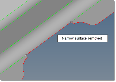
Flange narrow surface removal
|
|
|
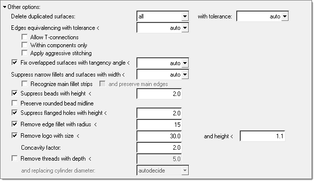
When Other Options is activated, the following options become enabled:
Option
|
Action
|
Delete duplicated surfaces
|
Options for deleting duplicate surfaces before meshing. Duplicates are determined using several options.
| • | All finds duplicates by considering all of the surfaces in all of the components against each other. |
| • | Within components only finds duplicates within components only. Duplicate surfaces between components are not found. |
| • | None prohibits duplicates surfaces from being removed. |
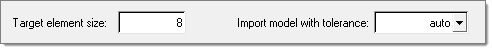
with tolerance defines the tolerance used when finding duplicates. It is defined in one of two ways:
| • | Auto calculates the tolerance automatically from the model size and other relevant geometric parameters. |
| • | <value> calculates the tolerance from a specified value. This is more useful when the auto tolerance is not sufficient to find all of the duplicates. |
|
Edges equivalencing with tolerance <
|
This defines the tolerance to use for equivalencing (stitching) edges, in conjunction with the options below. The auto option calculates the tolerance internally, while manual setting of the tolerance may be more useful when the auto tolerance is not sufficient to make all of the necessary connections.
| • | Allow T-connections allows T-connections (non-manifold edges) to be created during the stitching process. |
| • | Within components only allows stitching only within components. Stitching between edges of different components is not allowed. |
| • | Apply aggressive stitching performs additional heuristic procedures for finding cracks and stitching of them with an increased auto-defined tolerance. This is useful for models that may be significantly "dirty", for example when midsurfacing does not do a good job. |
|
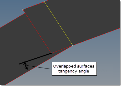
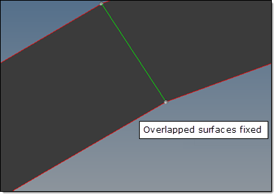
Fix overlapped surfaces with tangency angle <
|
This option gives you control of the embedded geometry cleanup tool and allows you to fix overlapping surfaces.
| • | Auto calculates the tangency angle internally. |
| • | <value> specifies a maximal tangency angle to fix overlapped surfaces. |
|
|
|
Overlapped surfaces fixed
|
Note: This option may remove the surfaces that should not be deleted. For example, it may happen to surfaces with T-connections. Setting the angle to < 45 may help reduce such side effects.
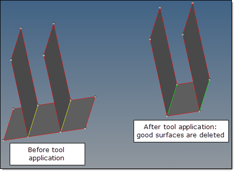
Possible side effects of fixing overlapped surfaces.
|
Suppress narrow fillets and surfaces with width <
|
This defines the width below which narrow fillets and surfaces are suppressed and combined into larger surfaces. The default "auto" value is 1.2 * minimal element size (except in the case of sharp features which are kept even with a width a bit less than the minimal element size). This value can be tuned to better match the mesh to the topology as needed. This option helps to eliminate sliver and tria elements.
| • | Recognize main fillet strips controls the recognition of wide fillet strips that are significantly bigger than the fillet merging threshold. These fillets often contain narrow fillets. This option aims to preserve the main fillets while suppressing the narrow ones. The side effect is that more narrow fillets close to the minimum element size are not merged. |
| • | and preserve main edges tries to recognize the "main" boundary lines (the edges that are the boundary of large flat surfaces) for wide fillets. To preserve these edges from suppression and to prevent the movement of nodes off of them by element cleanup and smoothing, these edges are specially marked with this option. The side effects are that generally the element quality worsens because of the introduction of new "hard" features. This is especially true when there are sliver elements between two feature lines which will no longer allow element cleanup to collapse them due to enabling this option. |
|
Suppress beads with height <
|
Turns on bead recognition and suppresses any beads with a height less than the specified value. This helps eliminate small elements and aids in creating a good mesh flow.
|
Preserve rounded bead midline
|
Enforces node placement along the midline of a rounded bead.
|
Suppress flanged holes with height <
|
Recognizes holes with small downward flanges, and eliminates those flanges with a height less than the specified value. Flanges with a height less than the minimal element size are extended to the minimal element size if not removed.
|
Remove edge fillet with radius <
|
Squares off any fillets/rounded edges located on free edges and having radii below the specified value. This helps to create a good mesh pattern in such areas. For concave fillets, this means material is removed. For convex fillets, this means material is added.
|
Remove logo
|
Removes small geometric features that represent logos in the model design. The following parameters are used to define and remove logos:
| • | with size < specifies the maximal size of a letter in the logo, as measured along/parallel to the "shiny" surface. |
| • | and height < specifies the maximal height/depth of a letter in the logo, as measured normal to the "shiny" surface. |
| • | Concavity factor creates a filter that provides more flexible control of automatic logo recognition. As this is a heuristic tool, it may remove real features (such as flat bottom round dimples) that were not intended for removal. |
The Concavity factor is a quantitative measure of a letters shape complexity, formally defined as:

The contour_accumulated_turn_angle is the sum of angles between a letters contour straight parts. Curved parts of a contour letter are approximated by a segmented line composed of short straight segments. For completely concave contour (such as circles, quads, and hexagons) concavity factor contour_accumulated_turn_angle = 360 degrees and concavity factor = 0.
To extend the recognition and removal of a logo, the Concavity factor should be reduced.
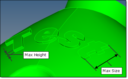
Logo removal parameters
|
Remove threads with depth <
|
Removes cylindrical or conical threads with a depth less than the specified value, and replaces them with a smooth cylinder or cone surface. The following options are used to define the diameter of the replacing cylinder or cone:
| • | autodecide selects the diameter of the replacing cylinder based on the diameter of a blank before thread cutting begins: |
| | For inner (hole) threads, it corresponds to the thread minor diameter. |
| | For outer (bold) threads, it corresponds to the thread major diameter. |
| • | major sets the diameter of the replacing cylinder/cone to the diameter of the thread major. |
| • | mean sets the diameter of the replacing cylinder/cone to the diameter of the thread mean. |
| • | minor sets the diameter of the replacing cylinder/cone to the diameter of the thread minor. |
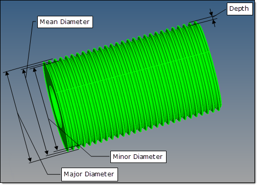
Thread removal parameters
|
|
|