Connector Definition |

|

|

|

|
|
Connector Definition |

|

|

|

|
The connector is simply a database of information defining a specific request for connection at a specific location.
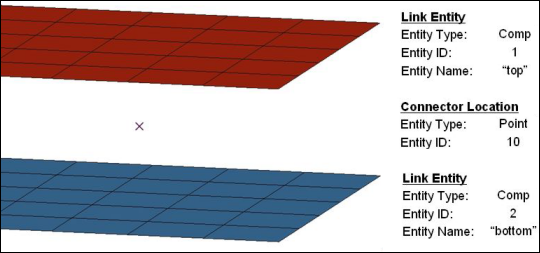
A connector definition describes the connector between multiple entities at a specific location. Entities that are to be connected are referred to as link entities. The connector location can be defined as a node or node list, a geometric point, a line or line list, a surface, or even as elements or tags. In the following example, there are two components (Top and Bottom) that are to be connected at the location of a point (with an id of 10). In this case, both components are considered to be link entities, since they are to be linked together. The point defines the location of the connector.

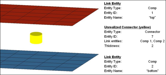
After a connector is created, the connector icon is placed at point 10, and components 1 and 2 are incorporated into the request for connection. The following diagram shows the connector after it is created (with an id of 7) at the location of point 10 (point 10 is not visible).

In this example, connector 7 has been defined and no welds have been created. The connector stores the following information:
| • | Which link entities the request for connection is to connect (Comp 1 and Comp 2) |
| • | The thickness of the realization (Thickness = 2) |
| • | Where to connect the link entities (the connector's current location) |
HyperMesh entities currently supported as link entities include PARTS, ASSEMS, COMPS, ELEMS, SURFS, NODES, and TAGS. Any number of link entities of differing types can be added to a connector in any order. The connector sets the order of link entities during the realization process.
The example above is a simple case where we have added two link entities of the same type (COMPS) to a single connector. For more detailed cases of connecting assemblies, see Example of Connecting Assemblies.
|
See Also: