In this tutorial, you will create the MADYMO leg model and define one of the body local coordinate systems.
Model Files
This tutorial uses the leg_geom.hm file, which can be found in <hm.zip>/interfaces/madymo/. Copy the file(s) from this directory to your working directory.
Exercise: Creating a MADYMO Model
Step 1: Load the MADYMO user profile
The MADYMO user profile configures the user interface to be MADYMO specific. The user profile also loads the XML import reader and MADYMO template file. The template file defines MADYMO specific entity types and attributes versus generic entities.
| 1. | Open HyperMesh Desktop. |
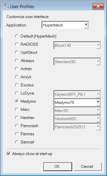
| 2. | In the User Profiles dialog, select Madymo. |
| 3. | Set the template drop-down to Madymo 70. |
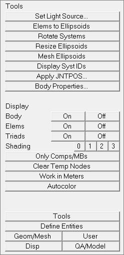
| 4. | Open the Utility menu by clicking View > Browsers > HyperMesh > Utility from the menu bar. |
Step 2: Retrieve the model file
The leg_geom.hm file contains IGES lines representing the layout of the leg and coordinate systems for bodies and joints.
| 1. | Open a model file by clicking, File > Open > Model from the menu bar. |
| 2. | In the Open Model dialog, open the leg_geom.hm file. |
Step 3: Create coordinate systems
The leg_geom.hm file contains all the coordinate systems for defining the leg model, except the coordinate system for the femur body.
| 1. | From the menu bar, click Geometry > Create > Systems > Axis Direction. |
| 2. | In the panel area, use the origin selector to select the center node of the femur area. |
| 3. | Using the x-axis selector, select a node along the length of the leg. |
| 4. | Using the xy-plane selector, select the node along the foot. |
| 6. | Click return to exit the Systems panel. |
Step 4: Create the femur body
| 1. | In the Model browser, right-click and select Create > Multibody from the context menu. |
| 2. | In the Create multibody dialog, Name field, enter femur. |
| 3. | Set Card image to RIGID. |
| 4. | Using the Center of gravity: Node selector, select the highest, yellow temp node (at the center of the femur). |
| 5. | Set Creation method to Body system. |
| 7. | In the Card Image dialog, enter 6.0 in the MASS field and 0.1 in the moments of inertia field. |
| 8. | Click return to save changes to the body's card image and close the Card Editor. |
| 9. | Remain in the Multibody: Create panel. |
Step 5: Create the tibia body
While in the Multibody: Create panel from the previous exercise, complete the following steps:
| 1. | Enter tibia in the name= field. |
| 2. | Click card image = and select RIGID from the pop-up list. |
| 3. | Double-click N1 to enter the Node Vector Edit sub-panel. |
| 6. | Click the yellow system selection box under use this system: to make it active. |
| 7. | Select the orange coordinate system at the center of the tibia. |
| 8. | Click create/edit to create the body and bring it up in the Card Editor. |
| 9. | Set MASS to 5.0 and the moments of inertia to 0.1. |
| 10. | Click return to save the changes to the body's card image and close the Card Editor. |
| 11. | Remain in the Multibody: Create panel for the next exercise. |
Step 6: Create the ball body
While in the Multibody: Create panel from the previous exercise, complete the following steps:
| 1. | Enter ball in the multibody name = field. |
| 2. | Click card image = and select RIGID from the pop-up list. |
| 3. | Click once on N1 to make it the active selector. |
| 4. | Select the yellow temp node at the center of the ball. |
| 5. | Click the yellow system selection box under use this system: to make it active. |
| 6. | Click the system box again. In the Id= field that pops up, enter 7 to select the orange coordinate system at the ball center. |
| 7. | Click create/edit to create the body and bring it up in the Card Editor. |
| 8. | Set MASS to 0.1 and the moments of inertia to 0.01. |
| 9. | Click return to save changes to the body's card image and close the Card Editor. |
| 10. | Remain in the Multibody: Create panel for the next exercise. |
Step 7: Create the ground body
While in the Multibody: Create panel from the previous exercise, complete the following steps:
| 1. | Enter ground in the multibody name= field. |
| 2. | Click card image = and select RIGID from the pop-up list. |
| 3. | Double-click N1 to enter the Node Vector Edit subpanel. |
| 6. | Click the switch to change the value to use body’s local system. |
| 7. | Click create to create the body. |
| 8. | Click return to leave the Multibody: Create panel. |
Steps 8- 12: Creating Geometry
Step 8: Create the ground plane
SURFACE.PLANE is defined in the Planes panel.
| 1. | Click the Analysis page and within the safety subpanel, click on planes. |
| 2. | Type ground in the name = field. |
| 3. | Click color and select a color for the plane. |
| 4. | Double-click N1 to enter the Node Vector Edit subpanel. |
| 5. | Use the tab key to quickly move through the fields. Under N1, enter the following: |
| 6. | Under N2, enter the following: |
| 7. | Under N3, enter the following: |
| 9. | Click multibody= and select ground from the pop-up list. |
| 10. | Click create to create the plane. |
| 11. | Click return to leave the panel. |
Step 9: Create the femur ellipsoid
SURFACE.ELLIPSOID and SURFACE.CYLINDER are created in the Ellipsoids panel.
| 1. | While still in the safety module, click on ellipsoids. |
| 2. | Type femur in the base name = field. |
| 3. | Click color and select a color for the femur. |
| 4. | Click the triangle next to center: and select entities from the pop-up list. |
| 5. | With the node selector active, select the node at the center of the femur. |
| 7. | Set orientation: to body system. |
| Note: | If an ellipsoid is created while referencing the wrong body, it can be easily updated in the Organize panel. |
| 8. | Click multibody= and select femur from the body list. |
| 9. | Activate the ellipsoid radio button next to create:. |
| 10. | Click create to create the ellipsoid. |
| 11. | Remain in the Ellipsoids panel for the next exercise. |
Step 10: Create the tibia ellipsoid
While still in the Ellipsoids panel from the previous exercise, complete the following steps:
| 1. | Type tibia in the base name = field. |
| 2. | Click color and select a color for the tibia. |
| 3. | With the node selector active, select the node at the center of the tibia. |
| 5. | Keep orientation: set to body system. |
| 6. | Click multibody= and select tibia from the body list. |
| 7. | Activate the ellipsoid radio button next to create:. |
| 8. | Click create to create the ellipsoid. |
| 9. | Remain in the Ellipsoids panel for the next exercise. |
Step 11: Create the foot ellipsoid
While still in the Ellipsoids panel from previous exercise, complete the following steps:
| 1. | Type foot in the base name = field. |
| 2. | Click color and select a color for the foot. |
| 3. | With the node selector active, select the node at the center of the foot. |
| 5. | Change orientation: to system and click the system button to make it active. |
| 6. | Select the global triad at the lower left corner of the model window. |
| 7. | Keep multibody= set to tibia. |
| 8. | Activate the ellipsoid radio button next to create:. |
| 9. | Click create to create the ellipsoid. |
| 10. | Remain in the Ellipsoids panel for the next exercise. |
Step 12: Create the ball ellipsoid
While still in the Ellipsoids panel from the previous exercise, complete the following steps:
| 1. | Type ball in the base name = field. |
| 2. | Click color and select a color for the ball. |
| 3. | Click the triangle switch next to center: and select entities from the pop-up list. |
| 4. | Select the node at the center of the ball. |
| 6. | Change orientation: to body system. |
| 7. | Click multibody= and select ball from the body list. |
| 8. | Activate the ellipsoid radio button next to create:. |
| 9. | Click create to create the ellipsoid. |
| 10. | Click return to leave the Ellipsoids panel. |
Steps 13-15: Creating Joints
Step 13: Create the knee joint
Joints connecting bodies in a multi-bodied system are created in the create joints panel.
| 1. | While still in the safety subpanel, click on create joints. |
| 2. | Type knee in the name = field. |
| 3. | Click type = and select REVO from the pop-up list. |
| 4. | Click the syst entity selection box under parent: and select the joint parent coordinate system by clicking on the coordinate system origin at the knee and selecting the purple parent coordinate system from the coincident selection circle. You can also single-click the syst button and enter 4 in the id= field that appears. |
| 5. | Click the syst entity selection box under child: to make it active. |
| 6. | Select the joint child coordinate system by clicking on the coordinate system origin at the knee and selecting the cyan child coordinate system from the coincident selection circle. You can also single-click the syst button and enter 6 in the id= field that appears. |
| 7. | Click the multibody entity selection box under parent: to make it active. |
| 8. | Click on the femur ellipsoid in the model window to select its body as the parent body. |
| 9. | Click the multibody entity selection box under child: to make it active. |
| 10. | Click on the tibia ellipsoid in the model window to select its body as the child body. |
| 11. | Click create to create the joint. |
| 12. | Remain in the Multibody Joints panel for the next exercise. |
Step 14: Create the hip joint
While still in the Multibody Joints panel from the previous exercise, complete the following steps:
| 1. | Type hip in the name = field. |
| 2. | Keep type = set to REVO. |
| 3. | Click the syst entity selection box under parent: to make it active. |
| 4. | Select the joint parent coordinate system by clicking on the coordinate system origin at the hip and selecting the purple parent coordinate system from the coincident selection circle. You can also single-click the syst button and enter 3 in the id= field that appears. |
| 5. | Click the syst entity selection box under child: to make it active. |
| 6. | Select the joint child coordinate system by clicking on the coordinate system origin at the hip and selecting the cyan child coordinate system from the coincident selection circle. You can also single-click the syst button and enter 5 in the id= field that appears. |
| 7. | Click the toggle next to the multibody selection box under parent: to set the joint parent body to reference space. |
| 8. | Click the syst entity selection box under child: to make it active. |
| 9. | Click on the femur ellipsoid in the model window to select its body as the child body. |
| 10. | Click create to create the joint. |
| 11. | Remain in the Multibody Joints panel for the next exercise. |
Step 15: Create the ball joint
While still in the Multibody Joints panel from the previous exercise, complete the following steps:
| 1. | Type ball in the name = field. |
| 2. | Click type = and select FREE from the pop-up list. |
| 3. | Click the syst entity selection box under parent: and enter 8 in the id= field. |
| 4. | Click the syst entity selection box under child: and enter 9 in the id= field. |
| 5. | Keep the parent body set to reference space. |
| 6. | Click on the ball ellipsoid in the model window to select its body as the child body. |
| 7. | Click create to create the joint. |
| 8. | Click return to leave the panel. |
Steps 16-19: Defining Systems of Bodies
Step 16: Define the leg SYSTEM.MODEL
SYSTEM.MODEL, SYSTEM.REF_SPACE, and MADYMO are defined in the Assemblies panel. HyperMesh assemblies are collections of collectors. The SYSTEM, BODY, FE_MODEL structure can also be defined in the Model Browser. Launching the Model Browser before starting this section of exercises provides a visual reference for the model hierarchy.
| 1. | While still in the safety subpanel, click on assemblies. |
| 2. | Type leg_system in the assem name = field. |
| 3. | Click type = and select SYSTEM from the pop-up list. |
| 4. | Click the multibodies entity selection box to make it active. |
| 5. | Click on the femur and tibia ellipsoids in the graphics window to include their bodies in the system. Or, click the multibodies button again and select the femur and tibia bodies from the list and click select. |
| 6. | Click create to create the assembly. |
| 7. | Remain in the Assemblies panel for the next exercise. |
Step 17: Define the ball SYSTEM.MODEL
While still in the Assemblies panel from the previous exercise, complete the following steps:
| 1. | Type ball_system in the assem name = field. |
| 2. | Click type = and select SYSTEM from the pop-up list. |
| 3. | With the multibodies selection box active, select the ball ellipsoid to include its body in the system. Or, click the multibodies button again and select ball from the list and click select. |
| 4. | Click create to create the assembly. |
| 5. | Remain in the Assemblies panel for the next exercise. |
Step 18: Define SYSTEM.REF_SPACE
While still in the Assemblies panel from the previous exercise, complete the following steps:
| 1. | Type ref_space in the assem name = field. |
| 2. | Click type = and select SYSTEM from the pop-up list. |
| 3. | With the multibodies selection box active, select the ground plane to include its body in the system. Or, click the multibodies button again and select ground from the list and click select. |
| 4. | Click create/edit to create the assembly and bring it up in the Card Editor. |
| 5. | Click MODEL and select REF_SPACE from the pop-up list. |
| 6. | Click return to save changes made to the card image and close the Card Editor. |
| 7. | Remain in the Assemblies panel for the next exercise. |
Step 19: Define MADYMO MODEL assembly
While still in the Assemblies panel from the previous exercise, complete the following steps:
| 1. | Type MADYMO_Model in the assem name = field. |
| 2. | Click type= and select MADYMO from the pop-up list. |
| 3. | Click the assems entity selection box to make it active. |
| 4. | Click assems again to bring up the assemblies list. |
| 5. | Activate the leg_system, ball_system, and ref_space check boxes and click select. |
| 6. | Click create/edit to create the assembly and bring it up in the Card Editor. |
| 7. | Click on TIME_STEP and enter 1e-4. |
| 8. | Click return to save changes made to the card image and close the Card Editor. |
| 9. | Click return to leave the Assemblies panel. |
Step 20: Define the initial conditions and position the leg
| 1. | While still in the safety subpanel, click on dummy. |
| 2. | Activate the incremental radio button. |
| 3. | Click on the triangle switch next to the yellow selection box and select multibodies from the pop-up list. Multibodies is used for positioning ellipsoid rigid body models and comp is used to position finite element and facet dummy models. |
| 4. | Enter 10 in the increment field. |
| 5. | Select the femur ellipsoid. HyperMesh automatically searches up to the next joint in the hierarchy and down through all the joints, bodies, and ellipsoids below in the hierarchy. |
| • | using the < and > buttons next to x rot to rotate the hip child joint coordinate system about the x axis of the hip parent joint coordinate system. |
| • | entering rotation values in the current fields. |
| 7. | Select the tibia or foot ellipsoids. HyperMesh automatically searches up to the next joint in the hierarchy. |
| • | using the < and > buttons next to x rot to rotate the knee child joint coordinate system about the x axis of the knee parent joint coordinate system. |
| • | entering rotation values in the current fields. |
| 9. | Click return to leave the Dummy panel. |
Step 21: Apply gravity and create vector data in HyperMesh
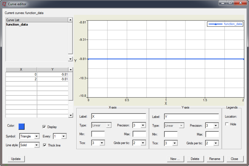
A gravity vector is applied by defining the vector in HyperMesh then applying the vector to a system of bodies in the Curve Editor.
| 1. | Click XY Plots > Curve Editor. |
| 3. | Enter function_data in the Name= field. |
| 5. | Select function_data in the top left corner. |
| 6. | In the table, in the first row, enter: |
| • | In the X column, enter 0 |
| • | In the Y column, enter -9.81 |
| 7. | In the second row of the table, enter |
| • | In the X column, enter 2 |
| • | In the Y column, enter -9.81 |
| 8. | Select a color, and activate the Display checkbox. |
| 9. | Set the Symbol field to Triangle. |
| 10. | Set the Line Style field to Solid, and activate the Thick line checkbox. |
| 12. | Click Close to close the Curve Editor. |
Step 22: Apply the gravity vector to the dummy
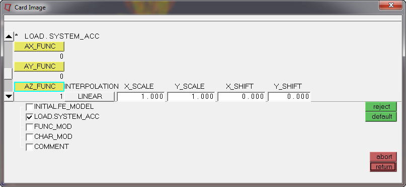
The gravity vector is applied by card editing the HyperMesh assembly which represents the dummy system of bodies.
| 1. | Right click on the leg_system assembly in the Model Browser and pick Card Edit. |
| 2. | Activate the LOAD.SYTEM_ACC checkbox. |
| 3. | Click once on the yellow AZ_FUNC curve selection box to make it active. |
| 4. | Click on AZ_FUNC and select function_data. |
| 5. | Click return to save the changes and leave the card image. |
| 6. | Click return to exit the Card Editor panel. |
| 7. | Repeat steps 1-5 for ball_system. |
Steps 23-25: Create ball ellipsoid characteristics
Ellipsoid characteristics are properties of ellipsoids and are defined as HyperMesh properties cards.
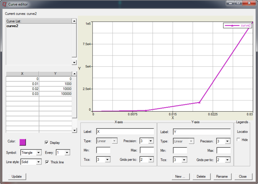
Step 23: Create the function curve using the Curve Editor
| 1. | Click XY Plots > Curve Editor. |
| 3. | Enter curve2 in the Name= field. |
| 5. | Select curve2 in the top left corner. |
| 6. | In the table, in the first row, enter: |
| • | In the X column, enter 0 |
| • | In the Y column, enter 0 |
| 7. | In the second row of the table, enter |
| • | In the X column, enter 0.01 |
| • | In the Y column, enter 1000 |
| 8. | In the third row of the table, enter |
| • | In the X column, enter 0.02 |
| • | In the Y column, enter 10000 |
| 9. | In the fourth row of the table, enter |
| • | In the X column, enter 0.03 |
| • | In the Y column, enter 100000 |
| 10. | Set the Symbol field to Triangle. |
| 11. | Set the Line style field to Solid. |
Step 24: Create the property for ellipsoid
| 1. | Right click in the Model Browser and pick Create > Property. |
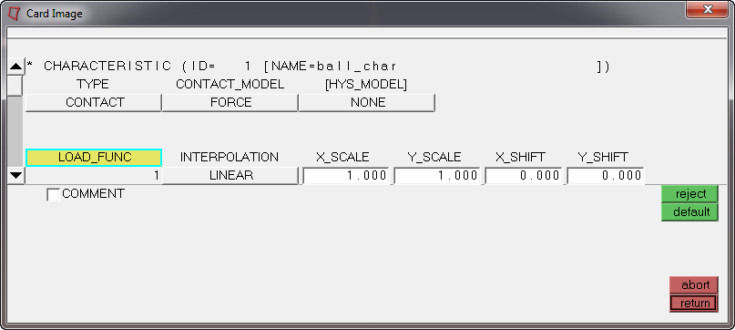
| 2. | Enter ball_char in the Name= field. |
| 3. | Click card image= and select CHAR from the pop-up list. |
| 4. | Click the Card edit property upon creation to activate the option |
| 5. | Click Create to create the property and open the Card Editor. |
| 6. | Click LOAD_FUNC and select the created characteristic curve2. |
| 7. | Click return to save the changes and exit the panel. |
Step 25: Assign the characteristic
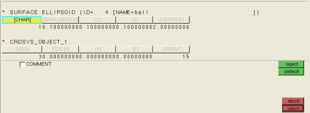
| 1. | Click the Card Edit icon  and click ellipsoids. and click ellipsoids. |
| 2. | Select the ball ellipsoid. |
| 4. | Click twice on CHAR to bring up the property list. |
| 6. | Click return to save the changes and exit the card image. |
| 7. | Click return to exit the Card Edit panel. |
Steps 26-30: Defining contacts
Contacts are created in the Contacts panel. A MADYMO GROUP consists of a single entity LIST or multiple LIST cards. LIST and GROUP cards are both defined in the HyperMesh Entity Sets panel.
Step 26: Create a GROUP for the foot contact surface
| 1. | Click Tools > Create > Sets. |
| 2. | Enter foot_ellipsoid_list in the name= field. |
| 3. | Click the toggle next to entity to set the selector to ellipsoids. |
| 4. | Graphically select the foot and tibia ellipsoids, or click ellipsoids and click on foot and tibia in the list. |
| 5. | Click create to create the entity set. |
| 6. | Click the toggle next to entity to set the selector to sets. |
| 7. | Enter lower_leg_group in the name= field. |
| 8. | Click on the sets selection box. |
| 9. | Activate the foot_ellipsoid_list check box and click select. |
| 10. | Click create to create the entity set. |
| 11. | Remain in the Entity Sets panel for the next exercise. |
Step 27: Create a GROUP for the ball contact surface
While still in the Entity Sets panel, complete the steps below:
| 1. | Enter ball_ellipsoid_list in the name= field. |
| 2. | Click the toggle next to entity to set the selector to ellipsoids. |
| 3. | Select the ball ellipsoid. |
| 4. | Click create to create the entity set. |
| 5. | Click the toggle next to entity to set the selector to sets. |
| 6. | Enter ball_group in the name= field. |
| 7. | Click on the sets selection box. |
| 8. | Activate the ball_ellipsoid_list check box and click select. |
| 9. | Click create to create the entity set. |
| 10. | Remain in the Entity Sets panel for the next exercise. |
Step 28: Create a GROUP for the ground contact surface
While still in the Entity Sets panel, complete the steps below:
| 1. | Enter ground_plane_list in the name= field. |
| 2. | Click the toggle next to entity to set the selector to mbplanes. |
| 3. | Select the ground plane by clicking on it in the model window or click mbplanes and click on ground and click select. |
| 4. | Click create to create the entity set. |
| 5. | Click the toggle next to entity to set the selector to sets. |
| 6. | Enter ground_group in the name= field. |
| 7. | Click on the sets selection box. |
| 8. | Activate the ground_plane_list check box and click select. |
| 9. | Click create to create the entity set. |
| 10. | Click return to leave the panel. |
Step 29: Define the Ball to Foot contact
| 1. | Click BCs > Create > Interfaces. |
| 2. | Activate the create radio button. |
| 3. | Enter ball_to_foot in the name= field. |
| 4. | Click type= and select MB_MB from the pop-up list. |
| 5. | Click create to create the contact definition. |
| 6. | Activate the add radio button. |
| 7. | Click twice on the master sets selection box. |
| 8. | Activate the ball_group check box and click select. |
| 9. | Click the master update button. |
| 10. | Click twice on the slave sets selection box. |
| 11. | Activate the lower_leg_group check box and click select. |
| 12. | Click the slave update button. |
| 13. | Remain in the Contacts panel for the next exercise. |
Step 30: Define the Ground to Ball contact
While still in the Contacts panel, complete the steps below:
| 1. | Click the create radio button to open the subpanel. |
| 2. | Enter ground_to_ball in the name= field. |
| 3. | Click type= and select MB_MB from the pop-up list. |
| 4. | Click create to create the contact definition. |
| 5. | Activate the add radio button. |
| 6. | Click twice on the master sets selection box. |
| 7. | Activate the ground_group check box and click select. |
| 8. | Click the master update button. |
| 9. | Click twice on the slave sets selection box. |
| 10. | Activate the ball_group check box and click select. |
| 11. | Click the slave update button. |
| 12. | Activate the card image radio button in the Contacts panel. |
| 13. | Click the green edit button. |
| 14. | Enter 0.1 for FRIC_COEF. |
| 15. | Click return to leave the Card Image panel. |
| 16. | Click return to exit the panel. |
Step 31: Export and run for finite time
| 1. | Right click on the MADYMO_Model assembly in the Model Browser and click Card Edit. |
| 2. | In the card image, enter 0.05 in the TIME_END field. |
| 3. | Click return to save the changes and exit the card image. |
| 4. | Click the Export Solver icon  to export the MADYMO file. to export the MADYMO file. |
| 5. | Use the file browser to specify an XML filename and click Save. |
| 6. | Solve the saved file using the MADYMO solver. |
| 7. | View the results by loading the KIN3 file in the |
See Also:
HyperMesh Tutorials


