In this tutorial, you will:
| • | Load the MADYMO user profile |
The MADYMO HyperMesh interface supports both the import and export of MADYMO files. A MADYMO XML file can be read using the Import tab. The model will be displayed. The model can be altered and the finished model can be written using the Export tab.
Model Files
This tutorial uses the following files, which can be found in <hm.zip>/interfaces/madymo/. Copy the file(s) from this directory to your working directory.
Exercise 1: Position the dummy
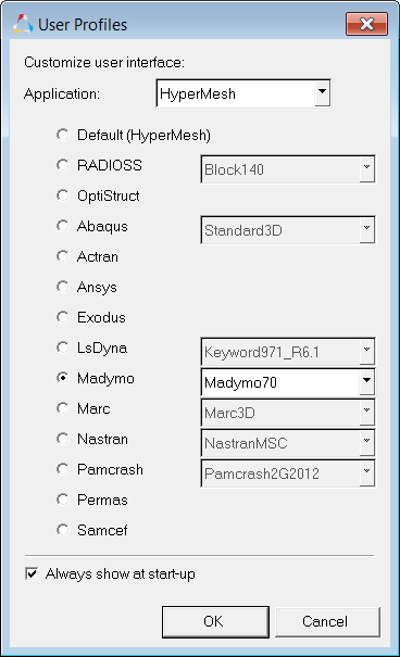
Step 1: Load the MADYMO user profile
The MADYMO user profile configures the user interface to be MADYMO specific. The user profile also loads the XML import reader and MADYMO template file. The template file defines MADYMO specific entity types and attributes versus generic entities.
| 1. | Upon opening, HyperMesh prompts you to select a user profile. Select the MADYMO profile. |
| 2. | Once the MADYMO profile is selected, the template drop down menu becomes activated. Select the MADYMO 70 template. |
| 4. | If the Utility Menu is not already displayed, click View > Browsers > HyperMesh > Utility to display it. |
Step 2: Import the file
The truck_model.xml file was created by converting an NCAC LS-DYNA truck model to MADYMO within the HyperMesh interface.
| 1. | Click File > Import > Solver Deck. |
| 2. | In the File: field, browse to the file truck_model.xml and click Open. |
| 3. | Click Import Options to expand the panel and display the advanced importing options. |
| 4. | Click on the Display Import Errors checkbox to deactivate this function. |
| 5. | Leave all other default settings as they are and click Import to import the model. |
| 6. | Remain in the Import tab. |
Step 3: Import the steering column file
The steering_column.xml file was created from scratch within the HyperMesh interface.
| 1. | In the File: field, browse to select the steering_column.xml file and click Open. |
| 2. | Leave all other default settings as they are and click Import to import the model. |
Step 4: Position the steering column
The Set Joints panel contains functionality for defining joint rotations and joint orientations for all joints plus global positioning for the highest joint in any system of bodies.
| 1. | From the Analysis page, click safety and then select the set joints subpanel. |
| 2. | Select the H-point subpanel. The H-point subpanel is used for defining global positioning for the highest joint in the system of bodies. |
| 3. | Make sure the yellow entity selection is set to multibody. To change, click on the triangle switch button next to the yellow entity selection box and select multibodies from the pop-up list. Comp is used to position finite element and facet dummy models. Multibody is used for positioning ellipsoidal rigid body models. |
| 4. | Click on any ellipsoid in the steering column. |
| 5. | In the Position fields, enter the following: |
| 6. | Click the green position button to set the position of the steering column. |
| 7. | Enter 180.00 in the increment field. |
| 8. | Click the triangle switch next to N1, N2, N3 and select z-axis from the pop-up window. |
| 9. | Click the green rotate+ button to rotate the steering column. |
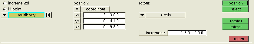
| 10. | Click return to exit the panel. |
Step 5: Import d_hyb350el_usr.xml
The d_hyb350el_usr.xml file is taken directly from your MADYMO installation. These files can be found in the path ...\share\dbs\dummies\3d folder in typical MADYMO installation.
| 1. | Click File > Import > Solver Deck. |
| 2. | In the File: field, browse to select the d_hyb350el_usr.xml file and click Open. |
| 3. | Click Import to import the model. |
Step 6: Position the dummy H-point
| 1. | From the Analysis page, click safety and then select the dummy subpanel. |
| 2. | Select the H-point subpanel. |
| 3. | Click on any ellipsoid in the dummy. |
| 4. | In the Position fields, enter the following: |
| 5. | Click the green position button to set the position of the dummy. |
| 6. | Enter 18 in the increment field. |
| 7. | Click the triangle switch under rotate: and select y-axis from the pop-up window. |
| 8. | Click the green rotate- button to rotate the dummy back against the seat. |
| 9. | Remain in the Dummy Positioning panel for the next exercise. |
Steps 7-10: Position the dummy limbs
You can quickly find the dummy limbs used in the steps below by using the Model Browser. Right-click on any entity and select Isolate to display only the part being manipulated.
Use the Dummy Positioning panel for the next series of steps.
Step 7: Rotate the femur ellipsoids
| 1. | Select the incremental subpanel. |
| 2. | Enter 10 in the increment field. |
| 3. | Click on a femur ellipsoid (FemurR_bod). HyperMesh automatically searches up to the next joint in the hierarchy. |
| 4. | Rotate the hip child joint coordinate system about the x, y, and z axes of the hip parent joint coordinate system by using y rot >. |
| 5. | Click the reset button  next to the multibody selection option. next to the multibody selection option. |
| 6. | Repeat the same for other femur ellipsoid (FemurL_bod). |
Step 8: Rotate the upper tibia
| 1. | Select the right upper tibia ellipsoid (tibiaUpR_bod). |
| 2. | In the y rot row, set the current field to -60 and click enter. |
| 3. | Repeat steps one and two for left upper tibia ellipsoid (tibiaUpL_bod). |
Step 9: Rotate the upper arm
| 1. | Select left upper arm ellipsoid (ArmUpL_bod). |
| 2. | In the x rot row, set the current field to -30 and click enter. |
| 3. | Repeat steps one and two for the right upper arm ellipsoid (ArmUpR_bod). |
Step 10: Rotate the lower arm
| 1. | Select the left lower arm ellipsoid (ArmLowL_bod). |
| 2. | In the x rot row, set the current field to -5 and click enter. |
| 3. | In the y rot row, set the current field to -70 and click enter. |
| 4. | Select the right lower arm ellipsoid (ArmLowR_bod). |
| 5. | In the x rot row, set the current field to 5 and click enter. |
| 6. | In the y rot row, set the current field to -70 and click enter. |
| 7. | Remain in the Dummy Positioning panel for the next exercise. |
Step 11: Set the steering wheel tilt
While still in the Dummy panel, complete the following steps:
| 1. | Activate the incremental radio button. |
| 2. | Enter 10 in the increment field. |
| 3. | Select an ellipsoid in the steering wheel. HyperMesh automatically searches up to the next joint in the hierarchy. |
| 4. | Click the rotate: toggle to change joint dof to joint orientation. |
joint dof rotates the child joint coordinate system locally about its axes and joint orientation rotates the parent joint coordinate system. Rotating the child joint coordinate system instead of the parent joint coordinate system to set the tilt will initiate an undesired initial torque. Rotation the parent joint coordinate system will temporarily "unlock" the joint.
| 5. | Use the < button next to x rot to set the tilt. |
| 6. | Set the rotate: toggle back to joint dof. |
| 7. | Click return to exit the panel. |
Step 12: Define the MADYMO/SYSTEM/FE MODEL hierarchy
Since three running MADYMO models were imported, extra INERTIAL_SPACE and MADYMO_MODEL blocks were defined.
| 1. | Click on the Model Browser. |
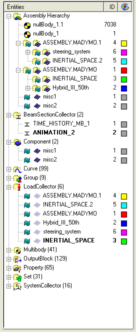
| 2. | Drag and drop truck_system and steering_system from ASSEMBLY.MADYMO and ASSEMBLY.MADYMO.1 respectively into the ASSEMBLY.MADYMO.2 folder. |
| 3. | Right-click and select delete on ASSEMBLY.MADYMO and ASSEMBLY.MADYMO.1. |
Steps 13 - 14: Applying a pulse function
A pulse function is applied by reading vector data from an external file source and applying the vector to a system of bodies in the card editor.
Step 13: Read the pulse data from an external file
HyperMesh can read vector data from the same file formats supported by HyperGraph. HyperMesh recognizes file types based on the file’s contents and automatically selects the correct reader to import the data.
| 1. | Click XYPlots > Create > Plots. |
| 2. | In the plot= field, enter acceleration_data. |
| 3. | Click create plot to create an empty plot window. |
| 4. | Click return to leave the Plots panel. |
| 5. | Click XYPlots > Edit > Plots. |
| 6. | Click on create to open the create subpanel. |
| 7. | In the file field, click load. Browse to the /hm/interfaces/madymo directory and select the file dummy_pulse.dat. |
| 8. | Activate the y= radio button. |
| 9. | Click the + button next to comp= to set the y component to Column 2. |
| 11. | Remain in the Edit Curves panel for the next exercises. |
Step 14: Apply the pulse vector to the dummy
The pulse vector is applied by card editing the HyperMesh assembly which represents the dummy system of bodies.
| 1. | Right click Hybrid_III_50th in the Model Browser and click Card Edit. |
| 2. | Activate the LOAD.SYSTEM_ACC checkbox. |
| 3. | Click once on the yellow AX_FUNC curve selection box. |
| 4. | Click on the pulse curve (curve1) in the plot window. |
| 5. | Click return to save the changes and leave the card image. |
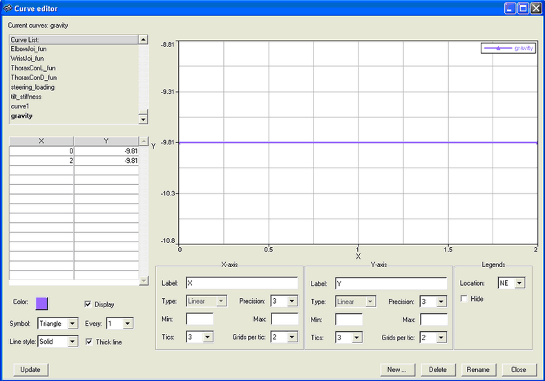
Steps 15 - 16: Applying gravity
A gravity vector is applied by defining the vector in HyperMesh then applying the vector to a system of bodies in the card editor.
Step 15: Create vector data in HyperMesh
| 1. | From the XY Plots menu, click on Curve Editor.... |
| 2. | Click on New... at the bottom of the window. |
| 3. | In the Name= field, enter gravity. |
| 5. | In the Curve Editor window, select gravity on the top left corner. |
| 6. | In the table, in the first row, enter: |
| • | In the X column, enter 0 |
| • | In the Y column, enter -9.81 |
| 7. | In the second row of the table, enter |
| • | In the X column, enter 2 |
| • | In the Y column, enter -9.81 |
| 8. | Select a color, and activate the Display checkbox. |
| 9. | Set the Symbol field to Triangle. |
| 10. | Set the Line style field to Solid, and activate the Thick line checkbox. |
| 12. | Click Close to close the Curve Editor. |
Step 16: Apply the gravity vector to the dummy
The gravity vector is applied by card editing the HyperMesh assembly which represents the dummy system of bodies.
| 1. | Right click the Hybrid_III_50th assembly in the Model Browser and click Card Edit. |
| 2. | Click once on the yellow AZ_FUNC curve selection box. |
| 3. | Click on the gravity curve (gravity) in the plot window. |
| 4. | Click return to save the changes and leave the card image. |
Steps 17 - 19: Defining contacts
Contacts are created in the contacts panel. A MADYMO GROUP consists of a single entity LIST or multiple LIST cards. LIST and GROUP cards are both defined in the HyperMesh Entity Sets panel.
Step 17: Create a contact entity
| 1. | Click BCs > Create > Interfaces. |
| 2. | In the name= field, enter seat_to_dummy. |
| 3. | Click type= and select MB_MB from the pop-up list. |
| 4. | Click create/edit to create the entity and bring up the card editor. |
Step 18: Define contact attributes
| 1. | In the FRIC_COEF field, enter 0.1. |
| 2. | Click on the box under CONTACT_TYPE and select MASTER from the pop-up list. |
| 3. | Click return to close to save the changes and close the card editor. |
Step 19: Add master and slave surfaces
| 1. | Click add to open the add subpanel. |
| 2. | Next to the master: field, click the yellow sets entity selection box twice to bring up a list of sets. |
| 3. | Activate the check box next to seat_gmb to make that the master surface. |
| 5. | Click update to the right of master: to update the master surface definition. |
| 6. | Next to the slave: field, click the yellow sets entity selection box twice to bring up a list of sets. |
| 7. | Activate the checkbox next to thorax_gmb and pelvis_gmb to use these as the slave surface. |
| 9. | Click update to the right of slave: to update the slave surface definition. |
| 10. | Repeat for other contacts. |
Steps 20 - 23: Adding Seatbelts
A seatbelt system can be created by scratch, or by importing and modifying and existing system. This exercise focuses on creating a seatbelt system in the seatbelt routing panel. When creating seatbelts from scratch, create a component of type BELT for each BELT_TYING or RETRACTOR point then connect the belt points in the seatbelt routing panel.
Step 20: Import belt_system.xml
The seatbelt_system.xml contains a running model of a single belt system.
| 1. | Click File > Import > Solver Deck. |
| 2. | In the File: field, browse to select the seatbelt_system.xml file and click Open. |
| 3. | Click Import to import the model. |
Step 21: Delete existing belt elements
The seatbelt_system.xml contains a running model of a single belt system.
| 1. | Press the F2 key to enter the Delete panel. |
| 2. | Set the yellow entity selector to elements. |
| 3. | Click elements and select by collector from the pop-up list. |
| 4. | Activate the check boxes next to fe_shoulder_belts and fe_lap_belts and click select. |
| 5. | Right click on the last lap belt LINE2 element attached to the constraint in the floor (left end of pelvis) to deselect it. |
| 6. | Click delete entity to delete the selected entities. |
| 7. | Click return to exit the panel. |
Step 22: Route the shoulder belt
| 1. | Enter the Seatbelt panel from the Safety panel. |
| 2. | Click G to open the Global panel. |
| 3. | Click component= and click fe_shoulder_belts in the component list. |
| 4. | Click return to leave the Global panel. |
| 5. | Select the node at the end of the BELT_SEGMENT element near the left shoulder. |
| 6. | Select the node at the end of the higher BELT_SEGMENT element near the buckle. |
| 7. | Click the ellipsoids entity selection button to make it active. |
| 8. | Click the ellipsoids in the thorax. Alternatively click the ellipsoids button again to display the ellipsoid list, select ellipsoids by collector, and click on all the bodies in the thorax. |
| 9. | Click orient to display the belt routing line segments. |
| 10. | Click on one of the red, end segments to activate it. |
| 11. | While holding the left mouse button, drag the mouse up and down to adjust the location of the belt segment. |
| 12. | Repeat the previous two steps for the other end segment and then the middle segment. |
| 13. | Click mesh to create the mesh. |
| 14. | Set using size= to 0.03. |
| 16. | Remain in the Seatbelt panel for the next exercise |
Step 23: Route the lap belt
| 1. | Click G to open the Global panel. |
| 2. | Click component= and click fe_lap_belts in the component list. |
| 3. | Click return to close the Global panel. |
| 4. | In the Seatbelt panel, select the node at the end of the LINE2 element near the floor constraint. |
| 5. | Select the node at the end of the lower BELT_SEGMENT element near the buckle. |
| 6. | Select the ellipsoids in the pelvis and abdomen. |
| 7. | Click orient to display the belt routing line segments. |
| 8. | Click on one of the red end segments to activate it. |
| 9. | While holding the left mouse button, drag the mouse up and down to adjust the location of the belt segment. |
| 10. | Repeat the previous two steps for the other end segment and then the middle segment. |
| 11. | Click mesh to create the mesh. |
| 12. | Set using size= to 0.03. |
| 13. | Click return to close the Seatbelt panel. |
Steps 24 - 27: Equivalence duplicate nodes
Many times it is preferred to use a duplicate node as the to or from node to define BELT_TYING. However, some times this feature is not preferred. Because inserting a coincident node is more difficult than equivalencing nodes, the seatbelt panel always uses a duplicate node. This training exercise does not use the duplicate node option in BELT_TYING so the duplicated nodes must be equivalenced.
Step 24: Replace nodes
| 1. | Click O to open the Options panel. |
| 2. | Click on the graphics subpanel. |
| 3. | Activate the coincident picking checkbox. |
| 4. | Click return to leave the Options panel. |
| 5. | Press F3 to enter the Replace panel. |
| 6. | Click a node selected as a to or from node in the Seatbelt panel. |
| 7. | In the selection circle, select the node with the lower ID. |
| 8. | Click on the same node location and select the other node from the coincident selection circle. |
| 9. | Repeat for the other three to and from nodes. |
| 10. | When finished, click return to close the panel. |
Step 25: Create a group multi-body for contacts
| 1. | Click Tolls > Create > Sets. |
| 2. | Set the yellow entity selector to nodes. |
| 3. | In the name= field, enter seatbelt_node_list. |
| 4. | Click on the nodes selection box and by collector from the pop-up list. |
| 5. | Activate the fe_shoulder_belts and fe_lap_belts check boxes and click select. |
| 6. | Click create to create the entity set. |
| 7. | Set the yellow entity selector to sets. |
| 8. | In the name= field, enter seatbelt_group. |
| 9. | Click on the sets selection box. |
| 10. | Activate the seatbelt_node_list check box and click select. |
| 11. | Click create to create the entity set. |
| 12. | Click return to leave the Entity Sets panel. |
Step 26: Define the contact
Applying MB_FE contacts is very similar to applying MB_MB contacts.
| 1. | Click BCs > Create > Interfaces. |
| 2. | In the name= field, enter dummy_to_belts. |
| 3. | Click type= and select MB_FE from the pop-up list. |
| 4. | Click create/edit to create the contact definition and bring it up in the card editor. |
| 5. | Set CONTACT_FORCE to KINEMATIC. |
| 6. | Under FRIC_COEF., enter 0.1. |
| 7. | Click return to save the changes and close the card editor. |
| 8. | Click the add subpanel. |
| 9. | Click the master sets selection box. |
| 10. | Activate the Shoulders_gmb, Thorax_gmb, Abdomen_gmb, and Pelvis_gmb check boxes and click select. |
| 11. | Click the master update button. |
| 12. | Click the slave sets selection box. |
| 13. | Activate the seatbelt_group check box and click select. |
| 14. | Click the slave update button. |
| 15. | Click return to close the Contacts panel. |
Step 27: Update the MADYMO/SYSTEM/FE MODEL hierarchy
Since three running MADYMO models were imported, extra INERTIAL_SPACE and MADYMO_MODEL blocks were defined.
| 1. | Click on the Model Browser. |
| 2. | Click and drag the Vehicle folder from its ASSEMBLY.MADYMO folder to the top ASSEMBLY.MADYMO.2 folder. |
| 3. | Click and drag slipring_seg and buckle_seg from their ASSEMBLY.MADYMO folder to the top ASSEMBLY.MADYMO.2 folder. |
| 4. | Right-click and select delete on ASSEMBLY_MADYMO. |
Step 28: Export and run for finite time
| 1. | Right click ASSEMBLY.MADYMO.2 in the Model Browser and click Card Edit. |
| 2. | In the card image, enter 0.05 in the TIME_END field. |
| 3. | Click return to save the changes and close the card image. |
| 4. | Click File > Export > Solver Deck. |
| 5. | In the file: field, enter an XML file name. |
See Also:
HyperMesh Tutorials


