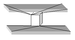
Washers
CFG nastran 56 bolts
*filter bolt
*style bolt 0
*head
rigidlink 1 1 dofs=123
rigidlink 1 3
*body 0
rigid 1 1 dofs=456
|
|
ACM Welds
CFG nastran 71 acm
*head
rbe3 0 0
*body 1
hex8 1 1
|
|
The above definition creates ACMs with HEXA8 solid elements as welds and RBE3 elements as rigids. The length of the hexa is equal to the distance between the connecting shell elements.
Series Welds
CFG nastran 101 series
*head
plot 0 0
*body 0
spring 6 0.5
spring 6 0.5
|
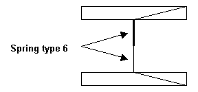
|
The two series welds are created with a length equal to half the distance between the link entities.
Series Welds
CFG nastran 101 series
*head
plot 0 0
*body 0
spring 6 0.5
|
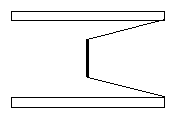
|
The series weld is created at the center with length equal to half the distance between the link entities.
Parallel Welds
CFG dyna 101 parallel
*head
plot 0 0
*body 0
bar2 1 1
bar2 1 1
|
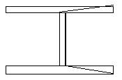
|
The bar elements are created at the same location and connect the same link entities.
0-D Welds
CFG pamcrash2g 1 plink (ce loc)
*head
plot 0 0
*body 0
mass 5 2
plot 0 1
*post prop_plink.tcl
|
|
Supported values for the length location flag are "0", "1", or "2". The behavior for each value is as follows, "0" places the 0-D element along the proposed 1-D element path. If this 0-D element is the only config given in the *body, then it is placed at the center of the proposed 1-D element path. "1" has the same behavior as "0" except only a single 0-D element is created even if multiple bodies are created (as happens in >2T welds) and "2" places the 0-D element at the connector location.
See Also:
FE Configuration File


