Feature mesh controls define the mesh density and quality of specific geometric features. These can be used to generate a high quality tria mesh on supported feature types.
Feature controls can be run standalone by right-clicking on the Feature folder and selecting the Mesh operation from the context menu. In this scenario:
| • | If a feature global control only exists, on-the-fly selection is prompted. |
| • | If a feature body control only exists, it must have a pre-defined selection and on-the-fly selection is not allowed. |
| • | If both a feature global and body control exist, the body control will always be used and the global control will be ignored. |
Feature controls can also be utilized along with other Surface Mesh controls by right-clicking on the Surface Mesh folder and selecting the Mesh operation from the context menu. In this scenario:
| • | A surface mesh model control is required. |
| • | The selection strictly comes from the surface mesh model control, either as a pre-defined selection or on-the-fly. |
| • | Only the surface mesh model control selection that overlaps with any feature selection (including body or local controls) is considered. |
| • | Feature global control will always be ignored in this case. |
It is recommended that feature controls be run standalone. Combined usage with other surface mesh controls may result in a non-conformal mesh.
Global mesh controls define the mesh for all geometry in the model, whereas body mesh controls define the mesh of selected local bodies.
Parameters
Parameter
|
Description
|
Average Element Size
|
The 2D element size in the model which controls the average element size.
|
Minimum Element Size
|
Minimum length of elements to generate in the mesh.
|
Coarse Mesh
|
Reduces the number of solid elements and the number of nodes. On an average, coarse mesh generates about 20 percent less nodes/elements compared to a regular volume mesher.
|
Use Maximum Element Size
|
Define the maximum element size instead of the average element size. Maximum element size = 1.4 * Average element size.
Only available for Global mesh controls.
|
|
Parameter
|
Description
|
Maximum Angle per Element
|
The approximation of a geometry is related to the angle made by an element edge on a perfect circle. For example, if the angle is 45 degrees this will approximate a circle by 8 elements. This same measurement is extended to an arbitrary curved surface.
|
Curvature Minimum Element Size
|
The mesh approximates the geometry by varying the mesh size as a function of the curvature. This geometry approximation cannot result in a mesh size smaller than the Curvature minimum element size.
|
|
Parameter
|
Description
|
Aspect Ratio
|
Determines the quality of the mesh. The value varies from 1 (equilateral element) to infinity (flat element). The default aspect ratio value is 10.
|
Mesh Grading
|
The variation of the mesh in the face from the boundary to the interior is controlled by the surface mesh grading. The default value is 1.5.
|
|
Parameter
|
Description
|
Element Type
|
Use Tria3 or Tria6 elements to create mesh.
|
Project Mid-node
|
Enables the projection of mid-nodes onto the faces and edges of the geometry.
|
Mesh Pattern
|
Determines the mesh pattern.
| • | Auto determines the faces that will be isomeshed automatically. All regular four edged faces and faces that are four sided will be isomeshed. |
| • | Regular 4-Sided Faces isomeshes all regular four edged faces, even if the edges are not of similar size. |
| • | None forces a free mesh on all faces in the body, even if it is a regular four edged face. |
|
|
|
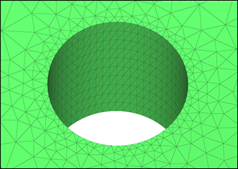
Cylinder mesh controls define the mesh both axially and in circular direction on selected cylindrical surfaces.
Parameters
Parameter
|
Description
|
Axial Mesh Size
|
Defines the element size along the length of the selected cylindrical faces.
|
Divisions
|
The number of nodes along the circular direction of the cylindrical face can be controlled by specifying the number of circular mesh seeds.
|
|
Edge mesh controls define the mesh on an edge.
Parameters
Parameter
|
Description
|
Divisions
|
Edge seeds are applied by specifying the number of elements.
|
|
Face mesh controls define the mesh on the selected local faces. A uniform mesh is generated on the face that has the face mesh control specified. The curvature is ignored.
Parameters
Parameter
|
Description
|
Average Element Size
|
The 2D element size in the model which controls the average element size.
|
Minimum Element Size
|
Minimum length of elements to generate in the mesh.
|
|
Parameter
|
Description
|
Maximum Angle per Element
|
The approximation of a geometry is related to the angle made by an element edge on a perfect circle. For example, if the angle is 45 degrees this will approximate a circle by 8 elements. This same measurement is extended to an arbitrary curved surface.
|
Curvature Minimum Element Size
|
The mesh approximates the geometry by varying the mesh size as a function of the curvature. This geometry approximation cannot result in a mesh size smaller than the Curvature minimum element size.
|
|
Parameter
|
Description
|
Aspect Ratio
|
Determines the quality of the mesh. The value varies from 1 (equilateral element) to infinity (flat element). The default aspect ratio value is 10.
|
Mesh Grading
|
The variation of the mesh in the face from the boundary to the interior is controlled by the surface mesh grading. The default value is 1.5.
|
Use Local
|
Uses the local settings when enabled. The settings from the global control will be used when disabled.
|
|
|
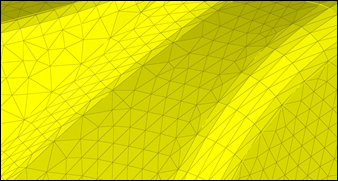
Fillet mesh controls define the mesh over fillets along the length and the curve direction. You can apply fillet mesh controls to selected faces or bodies.
Parameters
Parameter
|
Description
|
Length Along Fillet
|
Defines the element length along the length of the fillet.
|
|
Parameter
|
Description
|
Specification
|
Defines the element size along the fillet curvature direction.
| • | Number enables the Number of Elements option to explicitly indicate the number of elements along the curvature direction. |
| • | Curvature enables the Maximum Angle per Element and Curvature Minimum Element Size options for defining the mesh based on these values. |
|
|
Parameter
|
Description
|
Ignore Fillet Width Less Than
|
Specifies the minimum fillet width to consider. Fillets with a width below this value are ignored.
|
Aspect Ratio
|
Determines the quality of the mesh. The value varies from 1 (equilateral element) to infinity (flat element). The default aspect ratio value is 10.
|
Merge Small Fillets
|
Merges adjacent small fillets before meshing in order to improve the mesh quality.
|
Adjust Axial Length to Aspect Ratio
|
Adjusts the length along the fillet to make sure that the aspect ratio is satisfied.
|
|
|
Imprint circle mesh controls create a circular edge on a face with specified radius and seeds.
Parameters
Parameter
|
Description
|
Radius
|
Calculated using radius and scale factor values.
|
Scale
|
|
Divisions
|
Number of seeds along the circle.
|
|
Parameter
|
Description
|
Circle Center
|
Defines the center of the circular edge.
|
|
|
Isoline mesh controls place mapped mesh on cylindrical/conical faces that are trimmed. The mapped mesh is created for a given size/seed in axial and circular directions.
Parameters
Parameter
|
Description
|
Specification
|
Defines the given size/seed in axial and circular directions to create the mapped mesh.
|
|
Parameter
|
Description
|
Specification
|
The number of nodes along the circular direction can be controlled by using maximum angle or mesh seeds.
The maximum angle refers to the angle subtended by a circular spanning element edge from the axis of cylindrical face.
|
Merge Faces
|
Merges selected faces to a single face. Use this parameter to avoid the creation of a thin layer of elements when meshing.
|
|
Parameter
|
Description
|
Aspect Ratio
|
Determines the quality of the mesh. The value varies from 1 (equilateral element) to infinity (flat element). The default aspect ratio value is 10.
|
Curvature Minimum Element Size
|
The mesh approximates the geometry by varying the mesh size as a function of the curvature. This geometry approximation cannot result in a mesh size smaller than the Curvature minimum element size.
|
|
|
Preserved Entity mesh controls define the features to preserve while meshing. Tiny features on edges or surfaces may be collapsed if the minimum element size is larger than the feature. Entities selected here will be preserved from such collapsing.
|
Symmetry mesh controls are used to get identical mesh between the master face and symmetry face. If there are any discontinuous edges, select three nodes/vertices for both the master and symmetry face.
Parameters
Parameter
|
Description
|
Master Surface
|
Defines the surface to considered as the master/source for reflecting the mesh.
|
Symmetry Surface
|
Defines the surface to considered as the slave/target for reflecting the mesh.
|
Master Points
|
Defines points on the Master surface to be mapped in case there are any discontinuous edges.
|
Symmetry Points
|
Defines points on the Symmetry surface to be mapped in case there are any discontinuous edges.
|
|
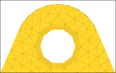
Washer mesh controls define rings around a circle. The circle has to be inside of a face.
Parameters
Parameter
|
Description
|
Washer Width
|
Define the width of the washer around the circle.
|
Number of Layers
|
Defines the number of mesh layers to create around the circle.
|
|


